3
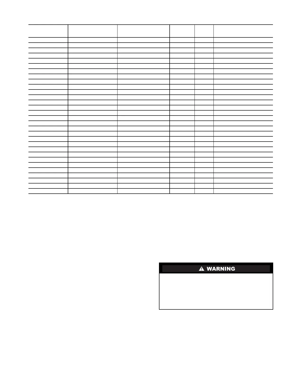
Table 1 — Positive Pressure System Assembly Numbers (R-134a)
LEGEND NOTES:
1. All storage vessels are 185 psig (1276 kPa) designs per the
ASME (American Society of Mechanical Engineers) Boiler Pres-
sure Vessel Code, Section VIII Division 1.
2. All units above are shipped with a 15 psig (103 kPa) nitrogen
charge.
3. Nominal horsepower for all pumpout units is 3.0.
Mount the Pumpout Unit — The pumpout unit, if
purchased separately, may be mounted directly on the chiller or
it may be floor mounted.
MOUNTING ON THE CHILLER — See instructions pro-
vided with the chiller for mounting the pumpout unit. A typical
chiller mount is shown in Fig. 2.
FLOOR MOUNTING — Select a ventilated and accessible
area, free of traffic or other hazards. Remove and discard the
4 angle supports at the base of the pumpout unit and bolt the
unit to the floor through the holes at the base of the pumpout
unit. Special isolation is unnecessary. Contact surface and
dimensions for the pumpout unit are given in Fig. 3.
Rig the Storage Tank — The complete 19XR system
can be rigged as a single assembly. See the rigging instructions
on the label attached to the assembly. Also refer to the rigging
guide (Fig. 4), physical data in Tables 2 and 3, and contact
surface and dimensions for the complete system in Fig. 5. Lift
the assembly only from the 4 points indicated in the rigging
guide. Each rigging cable must be capable of supporting the
entire weight of the assembly.
PUMPOUT SYSTEM
ARRANGEMENT
NUMBER
PUMPOUT UNIT
ASSEMBLY NUMBER
COMPRESSOR MOTOR
(V-Ph-Hz)
MAXIMUM
RLA
LRA STORAGE TANK
19XR04027401 19XR04026501 208/230-3-50/60 15.8 105.0 28 cu ft (0.8 cu m)
19XR04027402 19XR04026502 460-3-60 7.8 52.0 28 cu ft (0.8 cu m)
19XR04027403 19XR04026503 400-3-50 7.8 52.0 28 cu ft (0.8 cu m)
19XR04027501 19XR04026501 208/230-3-50/60 15.8 105.0 52 cu ft (1.5 cu m)
19XR04027502 19XR04026502 460-3-60 7.8 52.0 52 cu ft (1.5 cu m)
19XR04027503 19XR04026503 400-3-50 7.8 52.0 52 cu ft (1.5 cu m)
19XR04026801 19XR04026501 208/230-3-50/60 15.8 105.0 Free-standing
19XR04026802 19XR04026502 460-3-60 7.8 52.0 Free-standing
19XR04026803 19XR04026503 400-3-50 7.8 52.0 Free-standing
19XR14017801 19XR04026501 208/230-3-50/60 15.8 105.0 Unit-mounted, frame 1
19XR14017802 19XR04026502 460-3-60 7.8 52.0 Unit-mounted, frame 1
19XR14017803 19XR04026503 400-3-50 7.8 52.0 Unit-mounted, frame 1
19XR34017801 19XR04026501 208/230-3-50/60 15.8 105.0 Unit-mounted, frame 2 or 3
19XR34017802 19XR04026502 460-3-60 7.8 52.0 Unit-mounted, frame 2 or 3
19XR34017803 19XR04026503 400-3-50 7.8 52.0 Unit-mounted, frame 2 or 3
19XR44017801 19XR04026501 208/230-3-50/60 15.8 105.0 Unit-mounted, frame 4
19XR44017802 19XR04026502 460-3-60 7.8 52.0 Unit-mounted, frame 4
19XR44017803 19XR04026503 400-3-50 7.8 52.0 Unit-mounted, frame 4
19XR54017801 19XR04026501 208/230-3-50/60 15.8 105.0 Unit-mounted, frame 5
19XR54017802 19XR04026502 460-3-60 7.8 52.0 Unit-mounted, frame 5
19XR54017803 19XR04026503 400-3-50 7.8 52.0 Unit-mounted, frame 5
19XR64017801 19XR04026501 208/230-3-50/60 15.8 105.0 Unit-mounted, frame 6
19XR64017802 19XR04026502 460-3-60 7.8 52.0 Unit-mounted, frame 6
19XR64017803 19XR04026503 400-3-50 7.8 52.0 Unit-mounted, frame 6
19XR74017801 19XR04026501 208/230-3-50/60 15.8 105.0 Unit-mounted, frame 7
19XR74017802 19XR04026502 460-3-60 7.8 52.0 Unit-mounted, frame 7
19XR74017803 19XR04026503 400-3-50 7.8 52.0 Unit-mounted, frame 7
19XR84017801 19XR04026501 208/230-3-50/60 15.8 105.0 Unit-mounted, frame 8
19XR84017802 19XR04026502 460-3-60 7.8 52.0 Unit-mounted, frame 8
19XR84017803 19XR04026503 400-3-50 7.8 52.0 Unit-mounted, frame 8
LRA — Locked Rotor Amps
RLA — Rated Load Amps
Lifting the assembly from points other than those speci-
fied may result in serious damage to the assembly and
personal injury. Rigging equipment and procedures must
be adequate for assembly. See Tables 2 and 3 for weights.
(These weights are broken down into pumpout unit and
storage tank weights. For the complete assembly weight,
add all components together.)
 Loading...