6
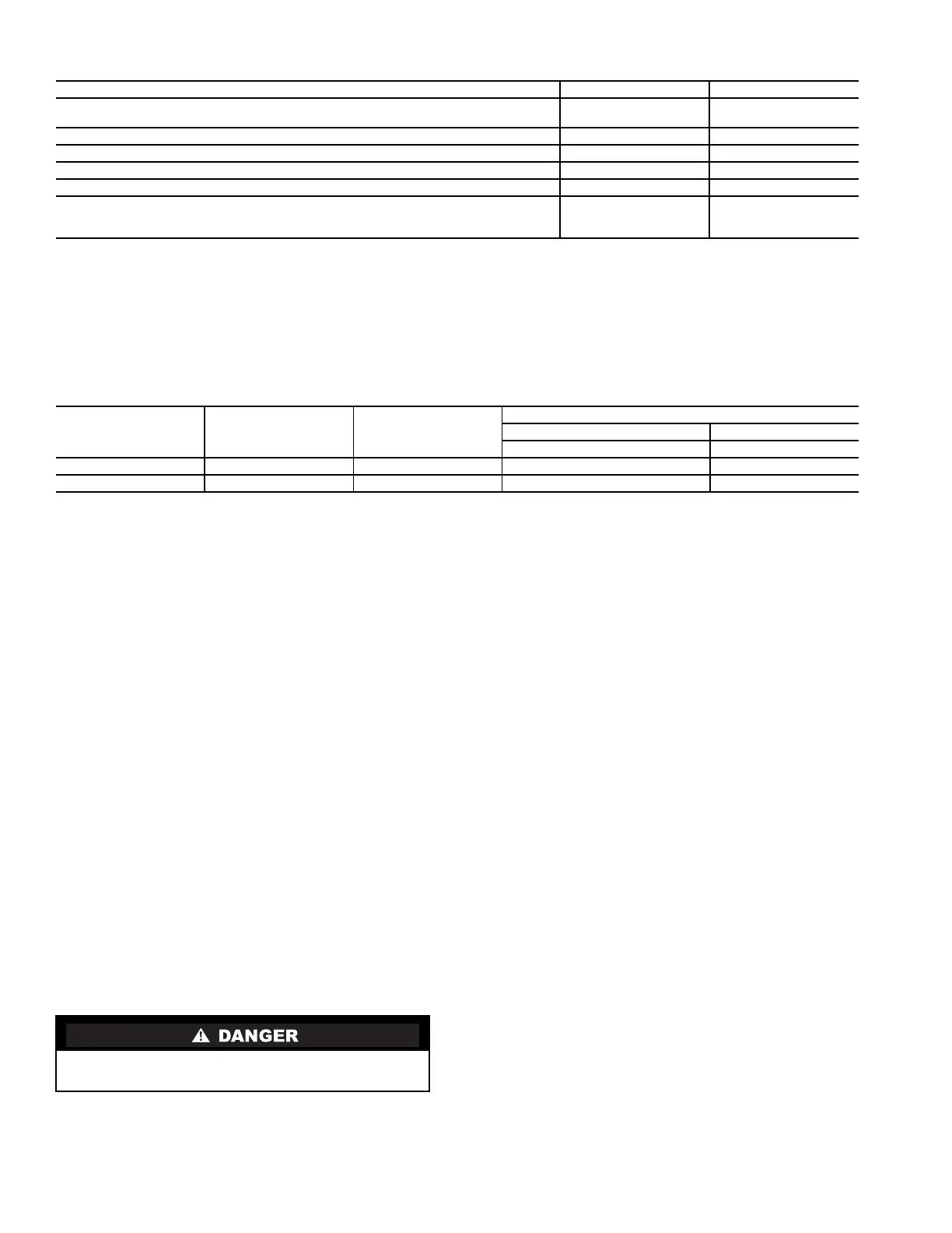
Table 2 — Physical Data — 19XR Pumpout Unit
*The pumpout unit weight includes the compressor/condenser, control box, and the oil separator.
NOTES:
1. The motor is hermetic with thermal protection.
2. The control box is mounted and wired with an ON/OFF/AUTO. switch according to NEMA 1 (National
Electrical Manufacturing Association).
3. The starter contactor is located in the control box. The overloads on the motor are wired and the
internal disconnect switch is supplied by the customer.
Table 3 — 19XR Storage Tank Rated Dry Weight and Refrigerant Capacity
LEGEND
*The above dry weight includes the pumpout unit weight of 164 lb (75 kg).
Make Piping Connections — Figure 6 represents typ-
ical pumpout unit/chiller piping connections. Standard connec-
tions for
1
/
2
-in. OD copper tubing are provided. Install the
field-supplied FPT tee with pipe plug in the piping as shown in
Fig. 6. This tee is used for refrigerant charging.
NOTE: If any field piping runs exceed 50 ft in length, use
7
/
8
-in. OD copper tubing to minimize pressure drop.
Pumpout unit water piping connections are shown in Fig. 6.
Both connections are
3
/
4
-in. NPT (female). A shutoff valve
should be installed in the water line. Provide a means for blow-
ing water from the condenser coil at winter shutdown to
prevent freeze-up damage. Refer to the Job Data for water
piping particulars.
INSTALL VENT PIPING TO RELIEF DEVICES — The
pumpout storage tank is factory-equipped with relief devices.
RefertoFig.5andTable4forsizeandlocationoftherelief
devices. Vent the relief devices to the outdoors in accordance
with ANSI/ASHRAE 15 Safety Code (latest edition) for
Mechanical Refrigeration and all other applicable codes.
Pumpout unit relief devices are set to relieve at 235 psig
(1620 kPa). Storage tank relief devices are set to relieve at
185 psig (1276 kPa).
1. If relief devices are manifolded, the cross-sectional area
of the relief pipe must at least equal the sum of the areas
required for individual relief pipes.
2. Provide a pipe plug near outlet side of each relief device
for leak testing. Provide pipe fittings that allow vent pip-
ing to be disconnected periodically for inspection of valve
mechanism.
3. Piping to relief devices must not apply stress to the
device. Adequately support piping. A length of flexible
tubing or piping near the device is essential on spring-
isolated machines.
4. Cover the outdoor vent with a rain cap and place a con-
densation drain at the low point in the vent piping to pre-
vent water build-up on the atmospheric side of the relief
device.
Make Electrical Connections — See nameplate on
compressor of pumpout unit and Table 1 for motor electrical
data. Wire unit according to the diagram inside the control box.
Figure 7 is the wiring schematic for a complete system that
includes the 19XR storage tank and the pumpout unit. Fig. 8 is
the wiring schematic for the pumpout unit. Use this schematic
for installations that do not include an auxiliary pumpout
storage tank.
NOTE: Use copper conductors only.
ENGLISH SI
Pumpout Unit Weight* lb (kg) 164 (75)
Pumpout Condenser Water Flow Rate gpm (L/s) 7-9 (.45-.58)
Pumpout Condenser Water Pressure Drop psig (kPa) 0.3 (2.0)
Maximum Entering Condenser Water Temperature F (C) 85 (29)
Maximum Leaving Condenser Water Temperature F (C) 100 (37)
Relief Valve psig (kPa) 235 (1620)
Condenser Pressure Rating
Refrigerant Side psig (kPa) 450 (3102)
Waterside psig (kPa) 450 (3102)
SIZE
cu ft (cu m)
TANK OD
in. (mm)
DRY WEIGHT*
lb (kg)
MAXIMUM REFRIGERANT CAPACITY lb (kg)
ASHRAE/ANSI 15 UL 1963
R-134a R-134a
28 (0.8) 24.00 (610) 2334 (1059) 1860 (844) 1716 (778)
52 (1.5) 27.25 (692) 3414 (1549) 3563 (1616) 3286 (1491)
ANSI — American National Standards Institute
ASHRAE — American Society of Heating, Refrigeration,
and Air Conditioning Engineers
UL — Underwriters’ Laboratories
Refrigerant discharged into confined spaces can displace
oxygen and cause asphyxiation.
 Loading...