Manufacturer reserves the right to discontinue, or change at any time, specifications or designs without notice and without incurring obligations.
PC 211 Catalog No. 531-984 Printed in U.S.A. Form 19XR-6SI Pg 16 7-04A 5-04 Replaces: 19XB-1SI
Book 2
Tab 5 a
Copyright 2004 Carrier Corporation
The pumpout oil separator comes pre-charged with 13 oz of
ISO viscosity 220 POE (Polyol Ester) oil. The pumpout com-
pressor is approved for use with ISO viscosity 220 POE oil or
ISO viscosity 68 POE oil. The pumpout compressor is also fac-
tory precharged with POE oil.
Oil should be visible in the pumpout compressor sight glass
both during operation and at shutdown. Always check the oil
level before operating the pumpout compressor. Before adding
or changing oil, relieve the refrigerant pressure through the ac-
cess valves.
Relieve refrigerant pressure and add oil to the pumpout unit
as follows:
1. Close service valves 2 and 4.
2. Run the pumpout compressor in Automatic mode for one
minute or until the vacuum switch is satisfied and com-
pressor shuts off.
3. Move the pumpout selector switch to OFF. Pumpout
compressor shell should now be under vacuum.
4. Oil can be added to the shell with a hand oil pump
through the access valve in the compressor base.
NOTE: Compressor access valve has a self-sealing fitting
which will require a hose connection with a depressor to open.
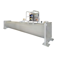
Storage Tank — To prevent moisture and contaminants
from entering the storage tank, maintain positive pressure in
the tank when not transferring refrigerant. Leak test the storage
tank periodically.
Ordering Replacement Parts — The following in-
formation must accompany an order for Carrier-specified parts:
• machine model number and serial number
• name, quantity, and part number of the part required
• delivery address and method of shipment
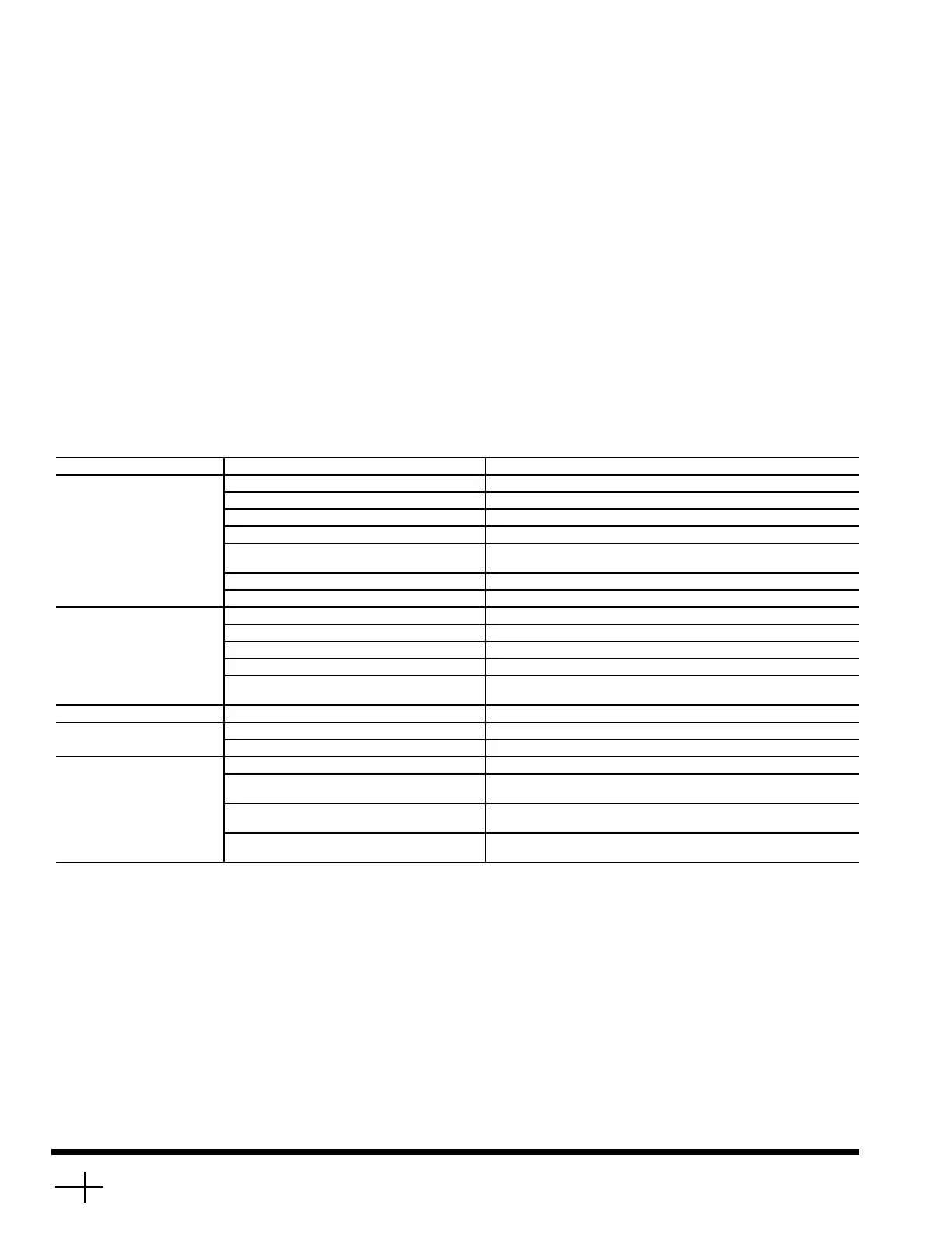
TROUBLESHOOTING
Information on troubleshooting for the PPS System is in-
cluded in Table 7.
Table 7 — Troubleshooting
SYMPTOM PROBABLE CAUSE REMEDY
Compressor Does Not Run Main power line open Replace fuse or reset circuit breaker.
Loose terminal connection Check connections.
Improperly wired controls Check wiring and rewire.
Low line voltage Check line voltage; determine location of voltage drop.
Compressor motor defective Check motor winding for open or short. Replace compressor if
necessary.
Seized compressor Replace compressor.
High level gage alarm Check refrigerant level and remove excess.
Compressor Cycles On
High-Pressure Control
High-pressure control erratic in action Check capillary tube for pinches. Set control as required.
Discharge valve partially closed. Open valve.
Air in system Purge system.
Condenser scaled. Clean condenser.
Condenser water pump or fans not
operating.
Start pump or fans.
Unit Operates Too Long Isolation valves partially open Close valves.
System Noises Piping vibrations Support piping as required. Check for loose pipe connectors.
Insufficient compressor oil Add oil.
Compressor Loses Oil Leak in system Locate and repair leak.
Plugged or stuck compressor oil return check
valve
Repair or replace valve.
Liquid refrigerant carries oil out of
compressor
Check to ensure only refrigerant vapor enters compressor suction
line. Add oil as necessary.
Motor shutdown on internal thermal protection
high temperature cutout.
High temperature cutout should reset within 120 minutes.
 Loading...