13
b. Turn off the pumpout condenser water, and turn on
the pumpout compressor in manual mode to push
liquid refrigerant out of the storage tank. Monitor
the storage tank level until the tank is empty.
c. Close refrigerant charging valves 7 and 10.
d. Turn off the pumpout compressor.
e. Turn off the chiller water pumps.
f. Close valves 3 and 4.
g. Open valves 2 and 5.
h. Turn on pumpout condenser water.
i. Run the pumpout compressor in manual mode until
the storage tank pressure reaches 5 psig (34 kPa),
18 in. Hg vacuum (41 kPa absolute).
j. Turn off the pumpout compressor.
k. Close valves 1a, 1b, 2, 5, and 6.
l. Turn off pumpout condenser water.
Transfer the Refrigerant from Chiller to Pumpout Storage
Tank
1. Equalize refrigerant pressure.
a. Valve positions:
b. Slowly open valve 5 and refrigerant charging
valves 7 and 10 to allow liquid refrigerant to drain
by gravity into the storage tank.
2. Transfer the remaining liquid.
a. Turn off pumpout condenser water. Place valves in
the following positions:
b. Run the pumpout compressor in automatic mode
until vacuum switch is satisfied and compressor
stops.
c. Turn off the pumpout compressor.
3. Remove any remaining refrigerant.
a. Turn on chiller water pumps.
b. Turn on pumpout condenser water.
c. Place valves in the following positions:
d. Run the pumpout compressor until the chiller pres-
sure reaches 35 psig (241 kPa); then, shut off the
pumpout compressor. Warm chiller condenser
water will boil off any entrapped liquid refrigerant
and chiller pressure will rise.
VALVE 1a1b2345671011
CONDITION C C C C
VALVE 1a1b2345671011
CONDITION CCCCCCCCC
VALVE 1a1b2345671011
CONDITION C C C C C
VALVE 1a1b2345671011
CONDITION C C
VALVE 1a1b2345671011
CONDITION C C
VALVE 1a1b2345671011
CONDITION C C C C
VALVE 1a1b2345671011
CONDITION C C C C
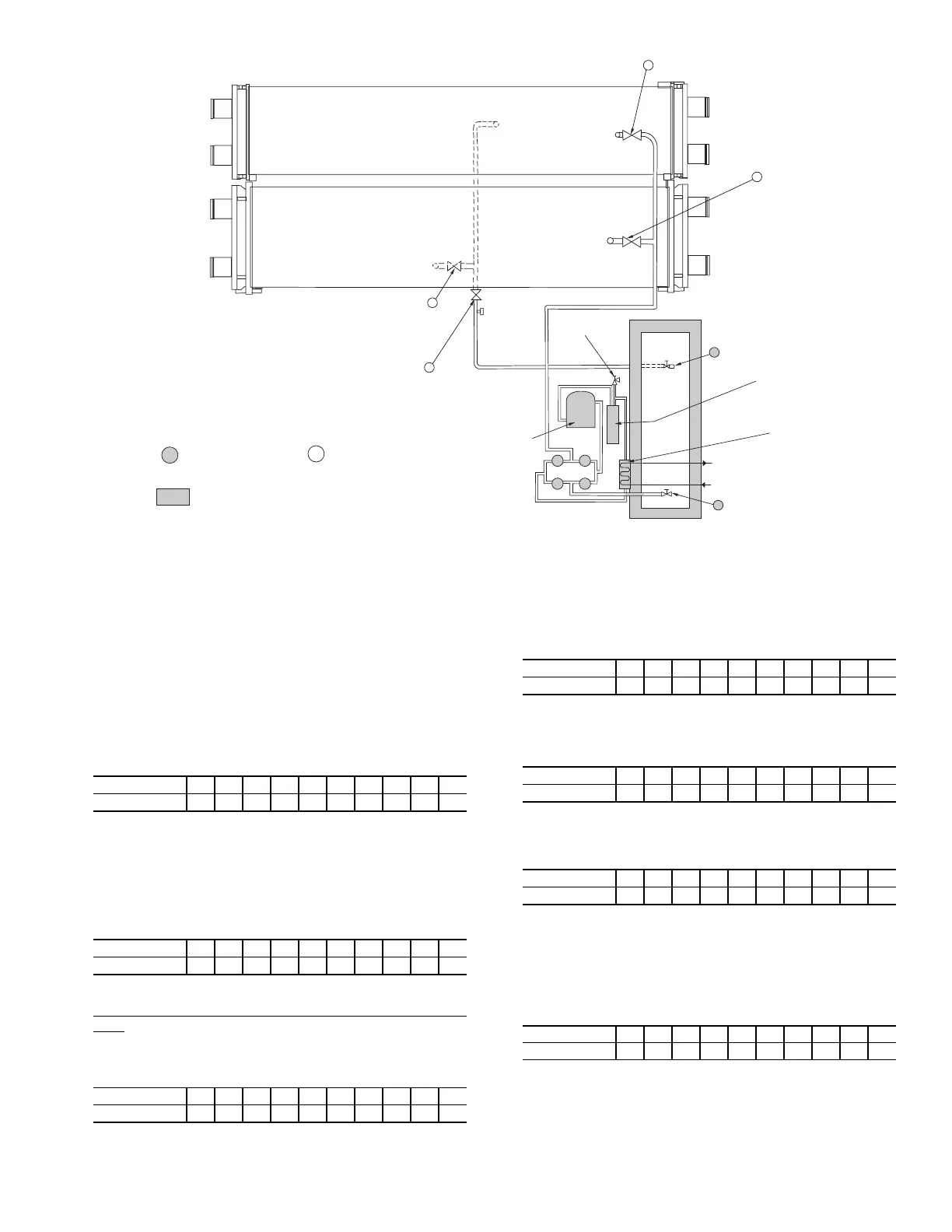
STORAGE
TANK LIQUID
VALVE
OIL
SEPARATOR
PUMPOUT
CONDENSER
WATER SUPPLY
AND RETURN
PUMPOUT
CONDENSER
STORAGE TANK
VAPOR VALVE
2
3
4
5
PRESSURE
RELIEF SAFETY
VALVE
PUMPOUT
COMPRESSOR
TEE FOR
CHARGING
SERVICE VALVE
COOLER
REFRIGERANT
ISOLATION
VALVE
REFRIGERANT
CHARGING
VALVE
CHILLER
CONDENSER
VESSEL
CHILLER
COOLER
VESSEL
10
6
7
11
1a
1b
SERVICE VALVE ON
PUMPOUT UNIT
=
SERVICE VALVE ON
CHILLER (FIELD
SUPPLIED)
=
=
MAINTAIN AT LEAST 2 FT (610mm) CLEARANCE AROUND
STORAGE TANK FOR SERVICE AND OPERATION WORK.
SERVICE VALVE
Fig. 10 — Valve Locations for 19XR Pumpout Unit With 19XB Storage Tank
 Loading...