103
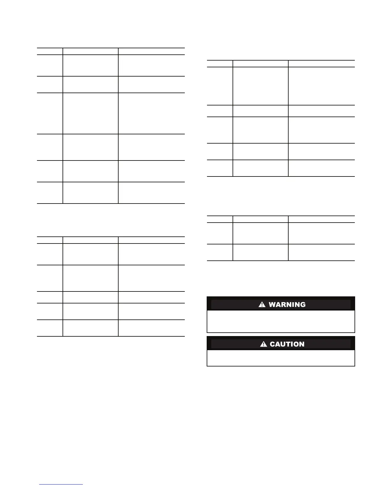
DRIVE STATUS INDICATOR — The DRIVE status indica-
tor is on the right side of the Gateway. See Table 19.
Table 19 — DRIVE Status Indicator
MS STATUS INDICATOR — The MS status indicator is the
second LED from the right of the Gateway. See Table 20.
Table 20 — MS Status Indicator: State Definitions
NET A STATUS INDICATOR — The NET A status indica-
tor is the third LED from the right of the Gateway. See
Table 21.
Table 21 — NET A Status Indicator:
State Definitions
NET B STATUS INDICATOR — The NETB status indicator
is the left LED on the Gateway. See Table 22.
Table 22 — NET B Status Indicator:
State Definitions
Physical Data — Tables 23A-31 and Fig. 48-58 provide
additional information on component weights, compressor fits
and clearances, physical and electrical data, and wiring sche-
matics for the operator’s convenience during troubleshooting.
STATE CAUSE CORRECTIVE ACTION
Off The Gateway is not
powered or is not con-
nected properly to the
drive.
• Securely connect the
Gateway to the drive using
the DPI ribbon cable.
• Apply power to the drive.
Flashing
Red
The Gateway is not
receiving a ping mes-
sage from the drive.
• Verify that cables are
securely connected.
• Cycle power to the drive.
Solid
Red
The drive has refused
an I/O connection from
the Gateway.
IMPORTANT: Cycle power
after making the following
correction:
• Verify that all DPI cables
on the drive are securely
connected and not dam-
aged. Replace cables if
necessary.
Orange The Gateway is con-
nected to a product that
does not support Rock-
well Automation DPI
communications.
• Check wires leading to the
A32 terminal block.
• Check that A32 terminal
block is fully engaged.
Flashing
Green
The Gateway is estab-
lishing an I/O connec-
tion to the drive or the
I/O has been disabled.
Normal behavior.
Solid
Green
The Gateway is prop-
erly connected and is
communicating with the
drive.
No action required.
STATE CAUSE CORRECTIVE ACTION
Off The Gateway is not
powered.
• Securely connect the
Gateway to the drive using
the ribbon cable.
• Apply power to the drive.
Flashing
Red
Recoverable Fault
Condition
Cycle power to the drive. If
cycling power does not cor-
rect the problem, the firm-
ware may need to be flashed
into the module.
Solid
Red
The module has failed
the hardware test.
• Cycle power to the drive
• Replace the Gateway
Flashing
Green
The Gateway is opera-
tional. No I/O data is
being transferred.
Normal behavior during SIO
configuration initialization
process.
Solid
Green
The Gateway is opera-
tional and transferring
I/O data.
No action required.
STATE CAUSE CORRECTIVE ACTION
Off The module is not pow-
ered or is not properly
connected to the
network.
First incoming network
command not yet
recognized.
• Securely connect the
Gateway ribbon cable to
the drive DPI board.
• Attach the RS485 cable in
Gateway to the connector.
• Apply power to the drive.
Flashing
Red
Network has timed out. Cycle power to the drive.
Solid
Red
The Gateway has
detected an error that
has made it incapable
of communication on
the network.
Check node address and
data rate switch positions on
the front of the Gateway.
Cycle power to the drive.
Flashing
Green
Online to network, but
not producing or con-
suming I/O information.
No action required. The LED
will turn solid green when
communication resumes.
Solid
Green
The module is properly
connected and commu-
nicating on the network.
No action required.
STATE CAUSE CORRECTIVE ACTION
Off Gateway not receiving
data over the network.
• Check wires leading to
A32 terminal block.
• Check that A32 terminal
block is fully engaged.
Solid or
Blinking
Green
Gateway is transmit-
ting data.
No action required.
Do not attempt to disconnect flanges while the machine is
under pressure. Failure to relieve pressure can result in per-
sonal injury or damage to the unit.
Before rigging the compressor, disconnect all wires enter-
ing the power panel.
 Loading...


