5
Factory-installed additional components are referred to as
options in this manual; factory-supplied but field-installed
additional components are referred to as accessories.
The chiller software part number of the 19XRV unit is
located on the back of the ICVC.
CHILLER FAMILIARIZATION
(Fig. 1 and 2)
Chiller Information Nameplate —
The information
nameplate is located on the right side of the chiller control
panel.
System Components — The components include the
cooler and condenser heat exchangers in separate vessels,
compressor-motor, lubrication package, control panel, and
VFD. All connections from pressure vessels have external
threads to enable each component to be pressure tested with a
threaded pipe cap during factory assembly.
Cooler — This vessel (also known as the evaporator) is
located underneath the compressor. The cooler is maintained at
lower temperature/pressure so evaporating refrigerant can
remove heat from water flowing through its internal tubes.
Condenser — The condenser operates at a higher
temperature/pressure than the cooler and has water flowing
through its internal tubes in order to remove heat from the
refrigerant.
Motor-Compressor — This component maintains sys-
tem temperature and pressure differences and moves the
heat-carrying refrigerant from the cooler to the condenser.
Control Panel — The control panel is the user interface
for controlling the chiller. It regulates the chiller’s capacity as
required to maintain proper leaving chilled water temperature.
The control panel:
• registers cooler, condenser, and lubricating system
pressures
• shows chiller operating condition and alarm shutdown
conditions
• records the total chiller operating hours
• sequences chiller start, stop, and recycle under micropro-
cessor control
• displays the status of the VFD
• provides access to other CCN (Carrier Comfort
Network®) devices and energy management systems
• languages pre-installed at factory include: English,
Chinese, Japanese, and Korean.
• International Language Translator (ILT) is available for
conversion of extended ASCII characters.
Variable Frequency Drive (VFD) — The VFD al-
lows for the proper start and disconnect of electrical energy for
the compressor-motor, oil pump, oil heater, and control panel.
Storage Vessel (Optional) — There are 2 sizes of
storage vessels available. The vessels have double relief valves,
a magnetically-coupled dial-type refrigerant level gage, a
one-inch FPT drain valve, and a
1
/
2
-in. male flare vapor con-
nection for the pumpout unit.
NOTE: If a storage vessel is not used at the jobsite, factory-
installed isolation valves on the chiller may be used to isolate
the chiller charge in either the cooler or condenser. An optional
pumpout system is used to transfer refrigerant from vessel to
vessel.
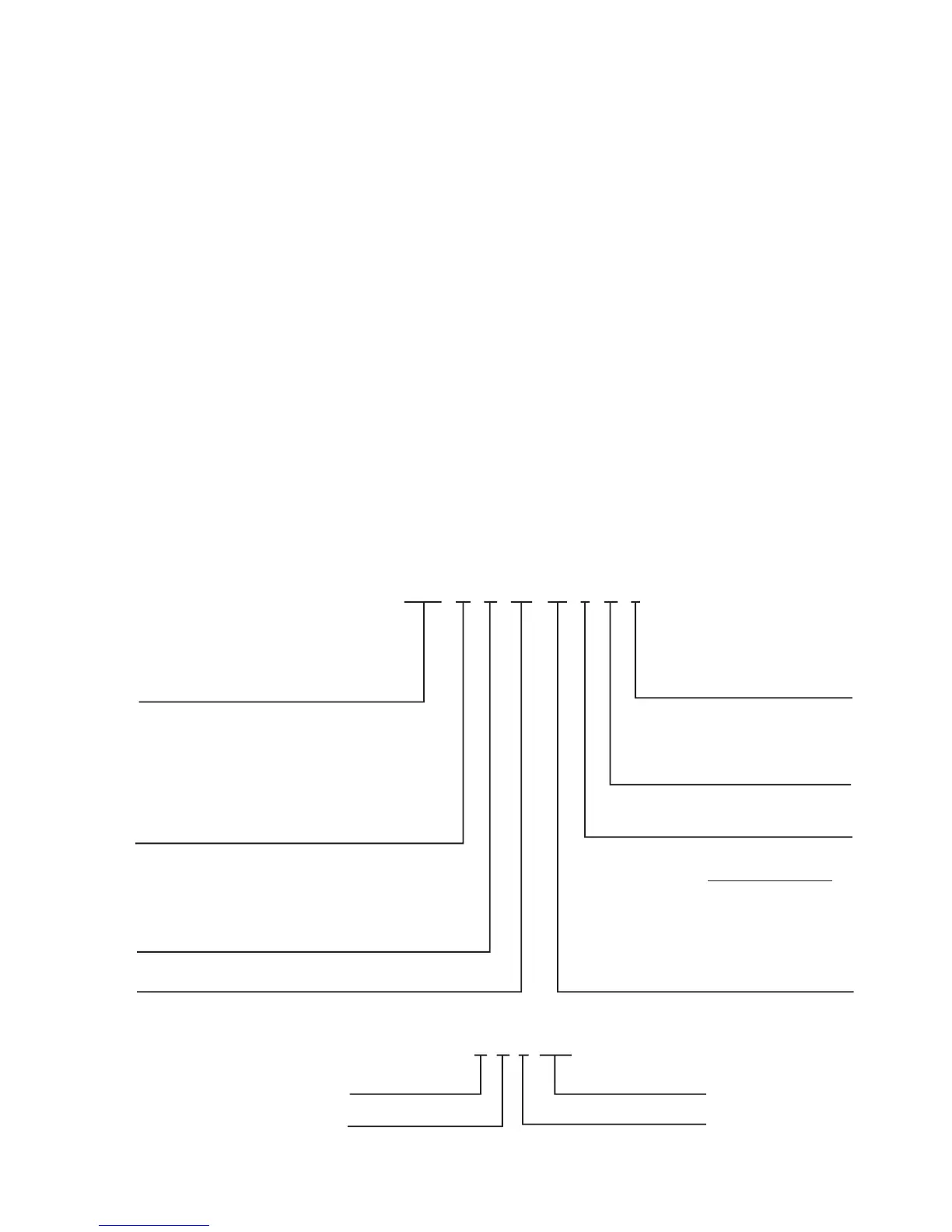
19XRV 52 51 473 DG H 64 –
19XRV — High Efficiency Hermetic
Centrifugal Liquid Chiller with
Variable Frequency Drive
Unit-Mounted
Condenser Size
20-22 (Frame 2 XRV)
30-32 (Frame 3 XRV)
35-37 (Frame 3 XRV)
40-42 (Frame 4 XRV)
45-47 (Frame 4 XRV)
50-52 (Frame 5 XRV)
55-57 (Frame 5 XRV)
60-62 (Frame 6 XRV)
65-67 (Frame 6 XRV)
70-72 (Frame 7 XRV)
75-77 (Frame 7 XRV)
80-82 (Frame 8 XRV)
85-87 (Frame 8 XRV)
Special Order Indicator
– — Standard
S — Special Order
Motor Voltage Code
Code Volts-Phase-Hertz
62 — 380-3-60
6
3 —416-3-60
64 — 460-3-60
52 — 400-3-50
Compressor Code
(First Digit Indicates Compressor Frame Size)*
Motor Efficiency Code
H — High Efficiency
S — Standard Efficiency
27 05 Q 71843
Week of Year
Year of Manufacture
Unique Number
Place of Manufacture
MODEL NUMBER NOMENCLATURE
SERIAL NUMBER BREAKDOWN
Cooler Size
20-22 (Frame 2 XRV)
30-32 (Frame 3 XRV)
35-37 (Frame 3 XRV)
40-42 (Frame 4 XRV)
45-47 (Frame 4 XRV)
50-52 (Frame 5 XRV)
5A (Frame 5 XRV)
5B (Frame 5 XRV)
5C (Frame 5 XRV)
55-57 (Frame 5 XRV)
5F (Frame 5 XRV)
5G (Frame 5 XRV)
5H (Frame 5 XRV)
60-62 (Frame 6 XRV)
65-67 (Frame 6 XRV)
70-72 (Frame 7 XRV)
75-77 (Frame 7 XRV)
80-82 (Frame 8 XRV)
85-87 (Frame 8 XRV)
*Second digit will be a letter (example 4G3) on units equipped with split ring diffuser.
Compressor Frame
2 3 3 4 4 5
BD
BE
BF
BG
BH
BJ
CD
CE
CL
CM
CN
CP
CQ
CR
KB
KC
KD
KE
KF
KG
KH
DB
DC
DD
DE
DF
DG
DH
DJ
DK
LB
LC
LD
LE
LF
LG
LH
EH
EJ
EK
EL
EM
EN
EP
EQ
Motor Code
Fig. 1 — 19XRV Identification
a19-1684
 Loading...


