71
Check Chiller Operating Condition — Check to be
sure that chiller temperatures, pressures, water flows, and oil and
refrigerant levels indicate the system is functioning properly.
Instruct the Customer Operator — Ensure the op-
erator(s) understand all operating and maintenance procedures.
Point out the various chiller parts and explain their function as
part of the complete system.
COOLER-CONDENSER — Float chamber, relief valves,
refrigerant charging valve, temperature sensor locations, pres-
sure transducer locations, Schrader fittings, waterboxes and
tubes, and vents and drains.
OPTIONAL PUMPOUT STORAGE TANK AND PUMP-
OUT SYSTEM — Transfer valves and pumpout system,
refrigerant charging and pumpdown procedure, and relief
devices.
MOTOR COMPRESSOR ASSEMBLY — Guide vane actu-
ator, transmission, motor cooling system, oil cooling system,
temperature and pressure sensors, oil sight glasses, integral oil
pump, isolatable oil filter, extra oil and motor temperature
sensors, synthetic oil, and compressor serviceability.
MOTOR COMPRESSOR LUBRICATION SYSTEM —
Oil pump, cooler filter, oil heater, oil charge and specification,
operating and shutdown oil level, temperature and pressure,
and oil charging connections.
CONTROL SYSTEM — CCN and LOCAL start, reset,
menu, softkey functions, ICVC operation, occupancy schedule,
set points, safety controls, and auxiliary and optional controls.
AUXILIARY EQUIPMENT — Disconnects, separate elec-
trical sources, pumps, and cooling tower.
DESCRIBE CHILLER CYCLES — Refrigerant, motor cool-
ing, lubrication, and oil reclaim.
REVIEW MAINTENANCE — Scheduled, routine, and ex-
tended shutdowns, importance of a log sheet, importance of
water treatment and tube cleaning, and importance of maintain-
ing a leak-free chiller.
SAFETY DEVICES AND PROCEDURES — Electrical dis-
connects, relief device inspection, and handling refrigerant.
CHECK OPERATOR KNOWLEDGE — Start, stop, and
shutdown procedures, safety and operating controls, refrigerant
and oil charging, and job safety.
REVIEW THE START-UP OPERATION, AND MAINTE-
NANCE MANUAL.
NOTE: Manuals and notebooks should not be stored under the
VFD power module as they will block airflow into the power
module cooling fan. Remove the manuals if they were placed
under the power module during shipping.
OPERATING INSTRUCTIONS
Operator Duties
1. Become familiar with the chiller and related equipment
before operating the chiller.
2. Prepare the system for start-up, start and stop the chiller,
and place the system in a shutdown condition.
3. Maintain a log of operating conditions and document any
abnormal readings.
4. Inspect the equipment, make routine adjustments, and
perform a Control Test. Maintain the proper oil and
refrigerant levels.
5. Protect the system from damage during shutdown periods.
6. Maintain the set point, time schedules, and other PIC III
functions.
Prepare the Chiller for Start-Up — Follow the steps
described in the Initial Start-Up section, page 70.
To Start the Chiller
1. Start the water pumps, if they are not automatic.
2. On the ICVC default screen, press the or
softkey to start the system. If the chiller is in the
OCCUPIED mode and the start timers have expired, the
start sequence will start. Follow the procedure described
in the Start-Up/Shutdown/Recycle Sequence section,
page 53.
Check the Running System — After the compres-
sor starts, the operator should monitor the ICVC display and
observe the parameters for normal operating conditions:
1. The oil reservoir temperature should be above 120 F
(49 C) during shutdown.
2. The bearing oil temperature accessed on the COMPRESS
table should be 120 to 165 F (49 to 74 C) for compressors
using journal bearings, and up to 175 F (79 C) for Frame
3 compressors equipped with rolling element bearings. If
the bearing temperature reads more than 180 F (83 C)
with the oil pump running, stop the chiller and determine
the cause of the high temperature. Do not restart the
chiller until corrected.
3. The oil level should be visible anywhere in one of the two
sight glasses. Foaming oil is acceptable as long as the oil
pressure and temperature are within limits.
4. The OIL PRESSURE should be between 18 and 30 psid
(124 to 207 kPad) differential, as seen on the ICVC
default screen. Typically the reading will be 18 to 25 psid
(124 to 172 kPad) at initial start-up. Typical values may
be up to 10 psid (69 kPad) higher for Frame 3 compres-
sors equipped with rolling element bearings.
5. The moisture indicator sight glass on the refrigerant
motor cooling line should indicate refrigerant flow and a
dry condition.
6. The condenser pressure and temperature varies with the
chiller design conditions. Typically the pressure will
range between 60 and 135 psig (390 to 950 kPa) with a
corresponding temperature range of 60 to 105 F (15 to
41 C). The condenser entering water temperature should
be controlled below the specified design entering
water temperature to save on compressor kilowatt
requirements.
7. Cooler pressure and temperature also will vary with the
design conditions. Typical pressure range will be between
60 and 80 psig (410 and 550 kPa), with temperature
ranging between 34 and 45 F (1 and 8 C).
LOCAL
CCN
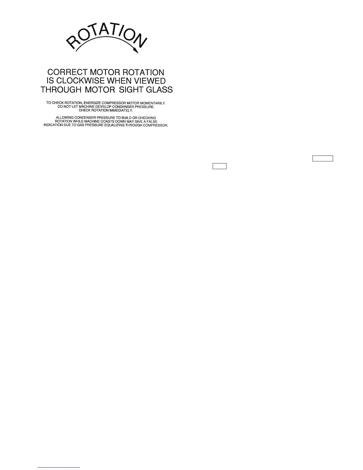
Fig. 37 — Correct Motor Rotation
a19-1326