Do you have a question about the Carrier 23XL and is the answer not in the manual?
Identifies the chiller model, serial number, and key specifications.
Lists and briefly describes the main components of the chiller system.
Explains the breakdown and meaning of the chiller's serial number.
Setting up the chiller's software and parameters for operation.
Configuring operational set points for the chiller's performance.
Setting the time schedule for local chiller operation.
Entering service-related parameters and settings for the chiller.
Calibrating pressure transducers and waterside flow devices for accurate readings.
Adjusting the refrigerant charge for optimal chiller performance.
Pre-start checks and verifications before initial chiller operation.
Performing a dry run to verify the start-up sequence.
Methods to prevent unintended chiller starts during service.
Provides a brief overview of the lubrication system.
Explains the specific components and functions of the oil system.
Explains how the slide valve controls capacity using oil pressure.
Describes the optional solid-state starter for reduced voltage starting.
Describes the optional wye-delta starter for reduced voltage starting.
Defines key terms like Analog Signal and Discrete Signal.
Overview of the microprocessor-based control system.
Details the components of the PIC II control system.
Explains how to operate the Chiller Visual Controller and navigate its menus.
Step-by-step guide to overriding values or statuses on the CVC.
Steps to remove an override and return to automatic control.
Accessing and using the service operation programs.
PIC II controls chiller capacity via slide valve based on water temperature.
Option to use entering chilled water temp for slide valve modulation.
Tolerance range for chiller control point to maintain temperature.
Adjusting slide valve response to temperature changes.
PIC II limits slide valve opening based on active demand limit set point.
How schedules determine chiller operation times.
Function of the shunt trip option as a safety trip mechanism.
Automatic chilled water temp reset based on remote sensor input.
Automatic chilled water temp reset based on remote sensor input.
Automatic reset based on cooler temperature difference.
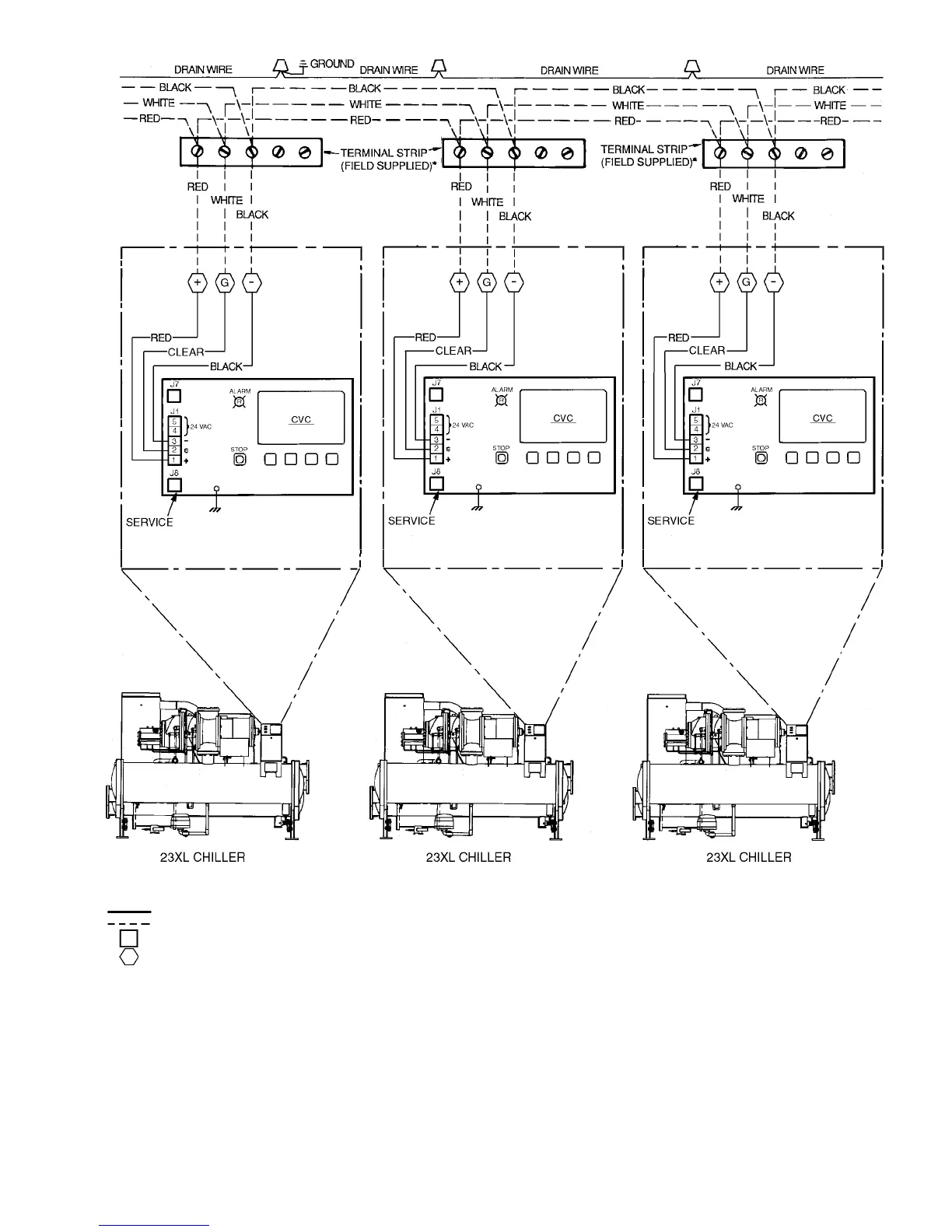
Lists requirements for implementing lead/lag control.
Information on installing common point sensors for lead/lag.
How to configure and operate lead/lag chillers.
How the ice build time schedule activates the ice build option.
Procedures for starting up or recycling during ice build.
How temperature is controlled during ice build.
Connecting and viewing other CCN modules.
Steps to access service screens, including password entry.
Initiating a local start-up sequence for the chiller.
List of essential job data needed before initial start-up.
List of tools and equipment needed for start-up.
Procedures for checking the chiller for leaks.
Method for pressurizing with dry nitrogen for leak testing.
Steps for leak testing when pressure is normal.
Steps for leak testing when pressure is abnormal.
Step-by-step guide for performing chiller dehydration.
Checks for mechanical starters, including wiring and connections.
Configuring operational set points for the chiller's performance.
Setting the time schedule for local chiller operation.
Entering service-related parameters and settings for the chiller.
Checking all thermistor temperature sensors.
Checking all pressure transducers.
Checking pump outputs and associated inputs.
Checking the slide valve operation.
Procedures for pumpdown and lockout.
Procedures to terminate pumpdown lockout.
Steps for calibrating cooler and condenser transducers.
Responsibilities of the chiller operator.
Steps to prepare the chiller before starting.
Procedure for starting the chiller.
Monitoring the chiller's operation after start-up.
Preparing for refrigerant transfer using pumpout systems.
Methods for reading refrigerant pressures during pumpout.
Transferring refrigerant to the condenser vessel.
Transferring refrigerant to the cooler vessel.
Transferring refrigerant from the pumpout tank to the chiller.
Transferring refrigerant from the chiller to the pumpout tank.
Methods for testing refrigerant leaks.
Leak testing after service or repairs.
Method for pressurizing with dry nitrogen for leak testing.
Observing oil levels in sight glasses weekly.
Resetting the service timer for tracking maintenance intervals.
General cleaning and tightening of connections for the control panel.
Procedures for changing the oil and oil filter.
Inspecting and cleaning cooler tubes.
Inspecting and cleaning condenser tubes.
Introduction to the PIC II features for troubleshooting.
Procedure to check sensor resistance.
Verifying sensor accuracy against a known temperature.
Steps for calibrating cooler and condenser transducers.
Viewing maintenance screens for control algorithms.
Testing various chiller outputs and controls.
Primary and secondary messages for manual stops.
Primary and secondary messages related to readiness for start-up.
Primary and secondary messages for recycle shutdowns.
Alerts that delay start-up, requiring correction.
Messages indicating the chiller is in the process of starting.
Messages indicating normal chiller operation.
Messages indicating normal operation with overrides active.
Alarms triggered by sensors outside their normal range.
Faults related to chiller protective limits.
Continues listing faults related to chiller protective limits.
Alerts related to chiller operations.
Continues listing alerts related to chiller operations.
Status indication of the STAT LED on modules.
Status indication of the COM LED on modules.
Describes the inputs for the Chiller Control Module.
Describes the outputs for the Chiller Control Module.
Describes the inputs for the Integrated Starter Module.
Describes the outputs for the Integrated Starter Module.
Steps for installing a replacement processor module.
Testing SCRs in Benshaw solid-state starters.
Weights of heat exchanger components.
Weights of the 23XL compressor assemblies.
Weights of various chiller components.