61
TO CHANGE THE PASSWORD — The password may be
changed from the CVC CONFIGURATION screen.
1. Press the and softkeys. Enter the
current password and highlight CVC CONFIGURA-
TION. Press the softkey. Only the last 5
entries on the CVC CONFIG screen can be changed:
BUS #, ADDRESS #, BAUD RATE, US IMP/METRIC
,
and
PASSWORD
.
2. Use the softkey to scroll to
PA S S W O R D
. The
first digit of the password is highlighted on the screen.
3. To change the digit, press the or
softkey. When the desired digit is seen,
press the softkey.
4. The next digit is highlighted. Change it, and the third
and fourth digits in the same way the first was
changed.
5. After the last digit is changed, the CVC goes to the
BUS
parameter. Press the softkey to leave that
screen and return to the SERVICE menu.
TO CHANGE THE CVC DISPLAY FROM ENGLISH TO
METRIC UNITS — By default, the CVC displays informa-
tion in English units. To change to metric units, access the
CVC CONFIGURATION screen:
1. Press the and softkeys. Enter the
password and highlight CVC CONFIGURATION.
Press the softkey.
2. Use the softkey to scroll to
US IMP/
METRIC
.
3. Press the softkey that corresponds to the units desired
for display on the CVC (e.g., US or METRIC).
MODIFY CONTROLLER IDENTIFICATION IF NECES-
SARY — The CVC module address can be changed from the
CVC CONFIGURATION screen. Change this address for each
chiller if there is more than one chiller at the jobsite. Write the
new address on the CVC module for future reference.
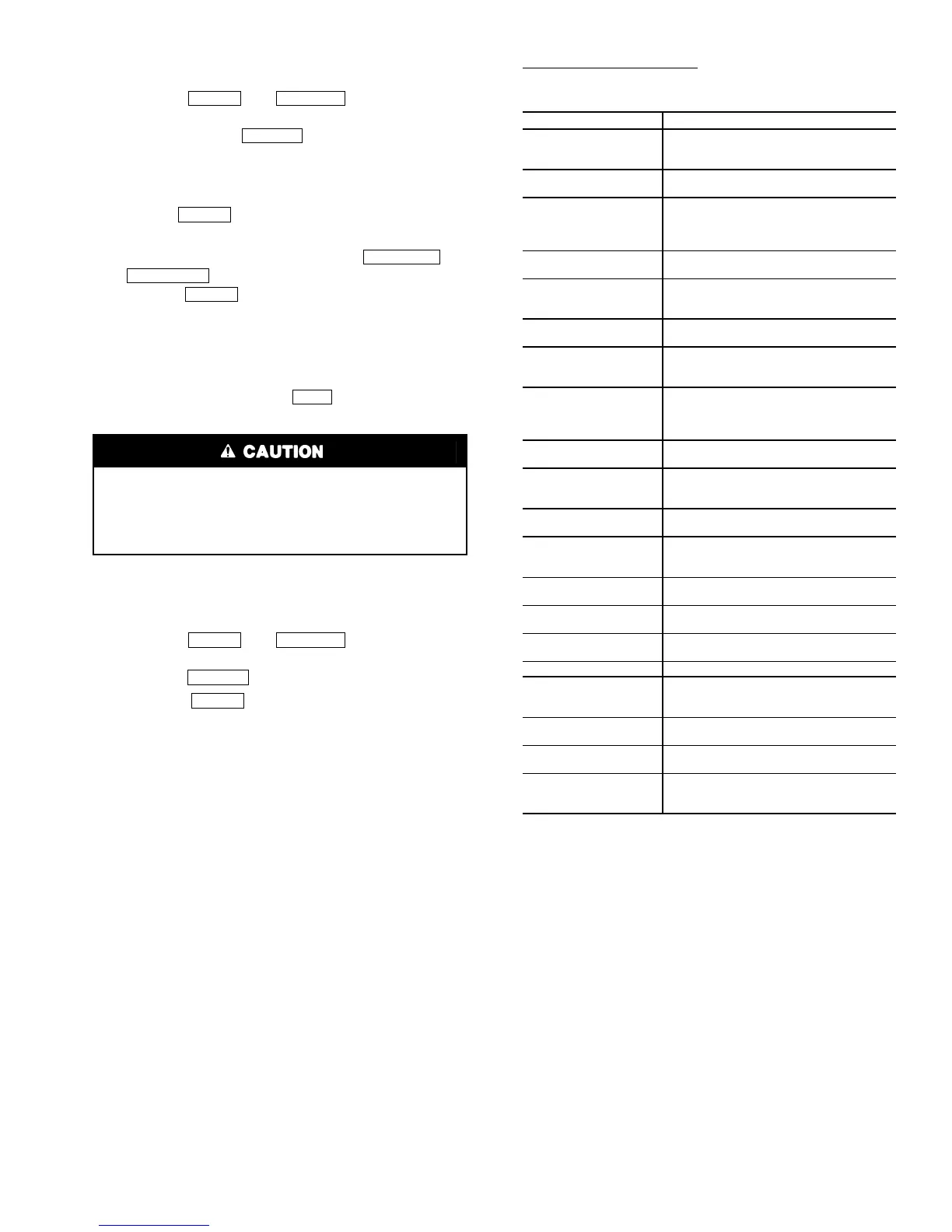
INPUT EQUIPMENT SERVICE PARAMETERS IF NEC-
ESSARY — The EQUIPMENT SERVICE table has six
service tables.
Configure SERVICE Tables
— Access the SERVICE tables,
depicted on the next page, to modify or view the following to
jobsite parameters:
*With variable flow systems this point may be configured to the lower
end of the range.
NOTE: Other parameters on these screens are normally left at the
default settings; however, they may be changed by the operator as
required. The time and persistence settings on the ISM_CONF table
can be adjusted to increase or decrease the sensitivity to a fault
condition. Increasing time or persistence decreases sensitivity.
Decreasing time or persistence increases sensitivity to the fault
condition.
Be sure to remember the password. Retain a copy
for future reference. Without the password, access to the
SERVICE menu will not be possible unless the
CVC_PSWD menu on the STATUS screen is accessed by
a Carrier representative.
MENU SERVICE
SELECT
ENTER
INCREASE
DECREASE
ENTER
EXIT
MENU SERVICE
SELECT
ENTER
PARAMETER TABLE
Starter Type
ISM_CONF — Select 0 for full voltage,
1 for reduced voltage, or 2 for solid
state/variable frequency drive.
Motor Rated Line
Voltage
ISM_CONF — Per chiller identification
nameplate data.
Volt Transformer
Ratio
ISM_CONF — Enter ratio (reduced to
a ratio to 1) of power transformer wired
to terminal J3 of ISM. If no transformer
is used enter 1.
Motor Rated
Load Amps
ISM_CONF — Per chiller identification
nameplate data.
Motor Locked
Rotor Trip
ISM_CONF — Per chiller identification
nameplate data. Enter locked rotor
delta amps (LR AMPS D-).
Starter LRA
Rating
ISM_CONF — Enter value from name-
plate in starter cabinet.
Motor Current
CT Ratio
ISM_CONF — Enter ratio (reduced to
a ratio to 1) of current transformers
wired to terminal J4 of ISM.
Ground Fault
Current
Transformers
ISM_CONF — Enter 0 if three ground
fault CTs are wired to terminal J5 of
ISM. Enter 1 if one ground fault CT is
used.
Ground Fault
CTRatio
ISM_CONF — Enter ratio (reduced to
a ratio to 1) of ground fault CT.
Single Cycle
Dropout
ISM_CONF — ENABLE if motor
protection required from drop in line
voltage within one cycle.
Line Frequency
ISM_CONF — Enter YES for 60 Hz or
NO for 50 Hz.
Line Frequency
Faulting
ISM_CONF — ENABLE if motor
protection required for drop in line
frequency.
Stall/Hot Gas
Bypass Option
OPTIONS — Default = 0 (Stall Limit)
Enter 1 if HGBP is installed.
Minimum Load
Points (T1/P1)
OPTIONS — Per job data — See mod-
ify load points section.
Full (Maximum)
Load Points (T2/P2)
OPTIONS — Per job data — See mod-
ify load points section.
Chilled Medium
SETUP1 — Enter water or brine.
Evaporator
Refrigerant
Trippoint
SETUP1 — Usually 3° F (1.7° C)
below design refrigerant temperature.
Evaporator Flow
Delta P Cutout
SETUP1 — Enter 50% of design pres-
sure drop to 0.5 psi (3.4 kPa).*
Condenser Flow
Delta P Cutout
SETUP1 — Enter 50% of design pres-
sure drop to 0.5 psi (3.4 kPa).*
Diffuser Option
SETUP2 — ENABLE for 5 size com-
pressor only. See model number
nomenclature.
 Loading...


