14
CONTROLS
Definitions
ANALOG SIGNAL —
An analog signal
varies in proportion
to the monitored source. It quantifies values between operating
limits. (Example: A temperature sensor is an analog device be-
cause its resistance changes in proportion to the temperature,
generating many values.)
DISCRETE SIGNAL —
A discrete signal
is a 2-position rep-
resentation of the value of a monitored source. (Example: A
switch produces a discrete signal indicating whether a value is
above or below a set point or boundary by generating an on/off,
high/low, or open/closed signal.)
General Controls Overview —
The 23XL hermetic
screw liquid chiller contains a microprocessor-based control
center that monitors and controls all operations of the chiller.
The microprocessor control system matches the cooling capac-
ity of the chiller to the cooling load while providing state-of-
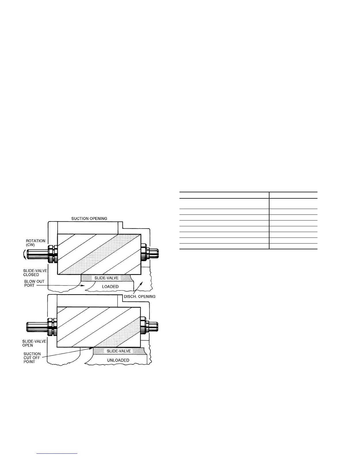
the-art chiller protection. The system controls cooling capacity
within the set point plus the deadband by sensing the leaving
chilled water or brine temperature and regulating the slide
valve via a mechanically linked, hydraulically actuated piston.
Movement of the slide valve alters the point during rotor travel
at which compression begins and reduces the effective length
of the compression cavities. This permits internal gas recircula-
tion and reduces suction volume. Thus, smooth, stepless capac-
ity regulation is provided in the load direction. Moving of the
slide valve increases capacity. Moving of the slide valve in the
unload direction decreases capacity. See Fig. 10. Chiller pro-
tection is provided by the processor, which monitors the digital
and analog inputs and executes capacity overrides or safety
shutdowns, if required.
PIC II System Components —
The chiller control
system is called PIC II (Product Integrated Control II). See Ta-
ble 2. The PIC II controls the operation of the chiller by moni-
toring all operating conditions. The PIC II can diagnose a prob-
lem and let the operator know what the problem is and what to
check. It promptly positions the slide valve to maintain leaving
chilled water temperature. It can interface with auxiliary equip-
ment such as pumps and cooling tower fans to turn them on
when required. It continually checks all safeties to prevent any
unsafe operating condition. It also regulates the oil heater while
the compressor is off and regulates the hot gas bypass valve, if
installed. The PIC II controls provide critical protection for the
compressor motor and controls the motor starter.
The PIC II can interface with the Carrier Comfort Network
(CCN) if desired. It can communicate with other PIC I or
PIC II equipped chillers and other CCN devices.
The PIC II consists of 3 modules housed inside 3 major
components. The component names and corresponding control
voltages are listed below (also see Table 2 and Fig. 11-16):
• control panel
all extra low-voltage wiring (24 v or less)
• power panel
230 or 115 v control voltage (per job requirement)
• starter cabinet
chiller power wiring (per job requirement)
Table 2 — Major PIC II Components and
Panel Locations*
*See Fig. 8 and Fig. 11-16.
CHILLER VISUAL CONTROLLER (CVC) — The CVC is
the “brain” of the PIC II. This module contains all the primary
software needed to control the chiller. The CVC is mounted to
the control panel (Fig. 15) and is the input center for all local
chiller set points, schedules, configurable functions, and op-
tions. The CVC has a stop button, an alarm light, four buttons
for logic inputs, and a backlight display. The backlight will au-
tomatically turn off after 15 minutes of non-use. The functions
of the four buttons or “softkeys” are menu driven and are
shown on the display directly above the softkeys. The CVC is
mounted in the Control Panel.
The angle of the control panel can be adjusted for optimum
viewing. Remove the 2 bolts connecting the control panel to
the brackets attached to the cooler. Place them in one of the
holes to pivot the control panel forward to backward to change
the viewing angle. See Fig. 15. To change the contrast of the
display, access the adjustment on the back of the CVC. See
Fig. 15.
PIC II COMPONENT PANEL LOCATION
Chiller Visual Controller (CVC) and
Display
Control Panel
Integrated Starter Module (ISM)
Starter Cabinet
Chiller Control Module (CCM)
Control Panel
Oil Heater Contactor (1C)
Power Panel
Hot Gas Bypass Relay (3C) (Optional)
Power Panel
Control Transformers (T1, T2)
Power Panel
Temperature Sensors
See Fig. 11 and 12.
Pressure Transducers
See Fig. 11 and 12.
Fig. 10 — Slide-Valve Capacity Control
 Loading...


