91
5. Using an ohmmeter, perform the following resistance
measurements and record the results:
If all measured values are greater than 5K ohms, pro-
ceed to Step 10. If any values are less than 5K ohms,
one or more of the SCRs in that pair is shorted.
6. Remove both SCRs in the pair (See SCR Removal/
Installation).
7. Using an ohmmeter, measure the resistance (anode to
cathode) of each SCR to determine which device has
failed.
NOTE: Both SCRs may be defective, but typically,
only one is shorted. If both SCRs provide acceptable
resistance measurements, proceed to Step 10.
8. Replace the defective SCR(s).
9. Retest the “pair” for resistance values indicated above.
10. On the right side of the firing card, measure the resistance
between the red and white gate/cathode leads for each
SCR (1 through 6). A measurement between 5 and
50 ohms is normal. Abnormally high values may indicate
a failed gate for that SCR.
11. Replace the SCRs and retest the pair.
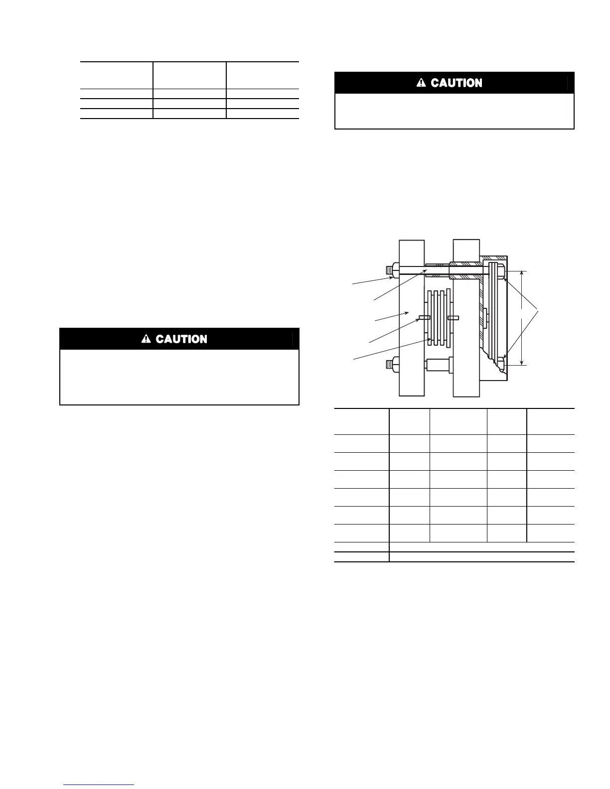
SCR REMOVAL/INSTALLATION — Refer to Fig. 45.
1. Remove the SCR by loosening the clamping bolts on
each side of the SCR,
2. After the SCR has been removed and the bus work is
loose, apply a thin coat of either silicon based thermal
joint compound or a joint compound for aluminum or
copper wire connections to the contact surfaces of the
replacement SCR. This allows for improved heat dissi-
pation and electrical conductivity.
3. Place the SCR between the roll pins on the heatsink
assemblies so the roll pins fit into the small holes in
each side of the SCR.
NOTE: Ensure the SCR is installed so the cathode side
is the side from which the red wire extends. The heat-
sink is labeled to show the correct orientation.
4. Hand tighten the bolts until the SCR contacts the heat
sink.
5. Using quarter-turn increments, alternating between
clamping bolts, apply the appropriate number of whole
turns referencing the table in Fig. 45.
6. Reconnect the red (cathode) wire from the SCR and
the white (anode-gate) wire to the appropriate location
on the firing card (i.e., SCR1 wires to firing card ter-
minal G1-white wire, and K1-red wire).
7. Reconnect all other wiring and bus work.
8. Return starter to normal operation.
MEASURE
BETWEEN
SCR PAIRS
BEING
CHECKED
RECORDED
VALUE
T1 and T6
3 and 6
T2 and T4
2 and 5
T3 and T5
1 and 4
If any red or white SCR gate leads are removed from the
firing card or an SCR, care must be taken to ensure the
leads are replaced EXACTLY as they were (white wires to
gates, and red wires to cathodes on both the firing card and
SCR), or damage to the starter and/or motor may result.
Care must be taken to prevent nut rotation while tightening
the bolts. If the nut rotates while tightening the bolt, SCR
replacement must be started over.
LOOSEN
AND
TIGHTEN
BOLTS
FROM
THIS END
CLAMPING
BOLT
NUT
ALUMINUM
HEATSINK
ROLL PIN
SCR
A
SCR PART
NUMBER
BISCR
CLAMP
SIZE
A
DIMENSION
(in.)
NO. OF
TURNS
BOLT
LENGTH
(in.)
6601218
1030
2.75
(70 mm)
1
1
/
2
3.0
(76 mm)
6601818
1030
2.75
(70 mm)
1
1
/
2
3.0
(76 mm)
8801230
1035
2.75
(70 mm)
1
3
/
4
3.5
(89 mm)
8801830
1035
2.75
(70 mm)
1
3
/
4
3.0
(89 mm)
15001850
2040
4.00
(102 mm)
2
3
/
4
4.0
(102 mm)
15001850
2050
4.00
(102 mm)
2
3
/
4
5.0
(127 mm)
220012100
Consult Benshaw Representative
330018500
Consult Benshaw Representative
Fig. 45 — SCR Installation

 Loading...


