5
ABBREVIATIONS AND EXPLANATIONS
Frequently used abbreviations in this manual include:
Words printed in all capital letters or in italics may be
viewed on the Chiller Visual Controller (CVC) (e.g., LOCAL,
CCN, ALARM, etc.).
Words printed in both all capital letters and italics can also
be viewed on the CVC and are parameters (e.g., CONTROL
MODE, COMPRESSOR START RELAY, ICE BUILD
OPTION, etc.) with associated values (e.g., modes, tempera-
tures, percentages, pressures, on, off, etc.).
Words printed in all capital letters and in a box represent
softkeys on the CVC control panel (e.g., , ,
, , etc.).
Factory-installed additional components are referred to as
options in this manual; factory-supplied but field-installed ad-
ditional components are referred to as accessories.
The chiller software part number of the 23XL unit is located
on the back of the CVC.
23XL CHILLER FAMILIARIZATION
(Fig. 1, 2A, and 2B)
Chiller Identification Nameplate —
The chiller
identification nameplate is located on the right side of the
chiller control panel center.
System Components —
The components include
cooler and condenser, heat exchangers in separate vessels,
motor-compressor, lubrication system, control panel, and
optional motor starter. All connections from pressure vessels
have external threads to enable each component to be pressure
tested with a threaded pipe cap during factory assembly.
CCM — Chiller Control Module
CCN — Carrier Comfort Network
CVC — Chiller Visual Controller
CCW — Counterclockwise
CW — Clockwise
ECDW — Entering Condenser Water
ECW — Entering Chilled Water
EMS — Energy Management System
HGBP — Hot Gas Bypass
I/O — Input/Output
ISM — Integrated Starter Module
LCD — Liquid Crystal Display
LCDW — Leaving Condenser Water
LCW — Leaving Chilled Water
LED — Light-Emitting Diode
OLTA — Overload Trip Amps
PIC II — Product Integrated Control II
RLA — Rated Load Amps
SCR — Silicon Controlled Rectifier
SI — International System of Units
ENTER
EXIT
INCREASE QUIT
LEGEND
VI —
Volumetric Index
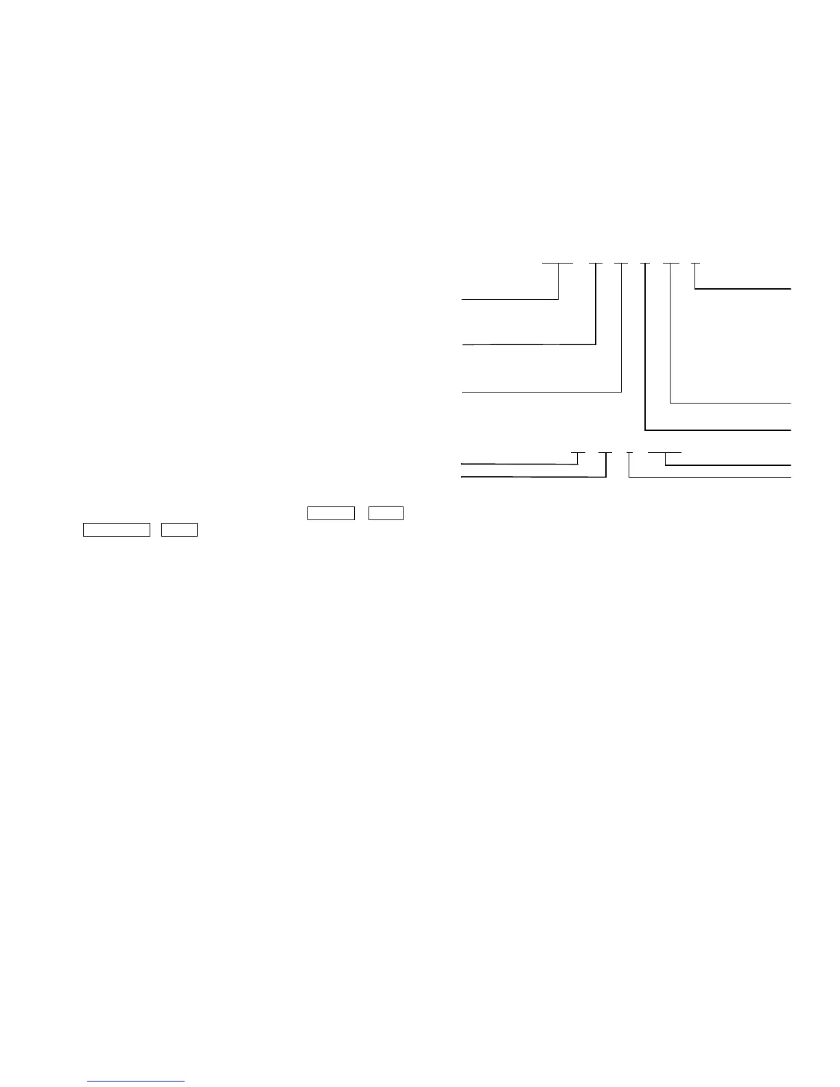
SERIAL NUMBER BREAKDOWN
Fig. 1 — 23XL Identification
23XL 21 21 E C6 0
Model Description
Hermetic Screw
Liquid Chiller
Cooler Size
10,11 — TC Frame 1
20, 21 — TC Frame 2
40,41,42,43 — TD Frame 4
Condenser Size
10,11 — TC Frame 1
20,21 — TC Frame 2
40,41,42,43 — TD Frame 4
1 — Variable V I
0 — Fixed V I
Compressor Size
C2 — 1260 Tons
(560 kW)
C4 — 200 Tons
(700 kW)
C6 — 250 Tons
(880 kW)
D4 — 300 Tons
(1055 kW)
D6 — 350 Tons
(1230 kW)
E — Economizer
N — No Economizer
99 28 J 59743
Year of Manufacture
Week of Year
Unique Number
Place of Manufacture
 Loading...


