NOTE:
Units equipped with variable speed drives (30RBP or 30RQP
or option 116V/116W)
If the air temperature is below -10 °C and the unit has been
de-energised for more than 4 hours, it is necessary to wait
two hours after the unit has been switched on again to allow
the variable drive to warm up.
7.2 - Minimum energy transfer uid ow rate
(units without factory-tted hydraulic module)
The minimum heat transfer uid ow rate for dierent unit sizes
is given in the tables in paragraph “Water type heat exchanger
ow rate”.
It is determined in order to allow sucient exchange and prevent
the risk of excessive fouling.
If the system ow rate is less than the unit's minimum ow rate,
the exchanger ow can be recirculated, as shown in the diagram.
Key
1 Water-cooled heat exchanger
2 Recirculation
7.3 - Maximum energy transfer uid ow rate
(units without factory-tted hydraulic module)
The maximum heat transfer uid ow rate for dierent unit sizes
is given in the tables in paragraph “Water type heat exchanger
ow rate”.
This is limited by the permitted exchanger pressure drop. In
addition, there must be a minimum Delta T of 2.8 K, which
corresponds to a ow rate of 0.09 l/s per kW.
If the system ow rate exceeds the unit's maximum value, it can
be bypassed as shown in the diagram.
Key
1 Water-cooled heat exchanger
2 Bypass
7.4 - Variable ow water type heat exchanger
(units without factory-tted hydraulic module)
A variable water heat exchanger ow can be used in standard
units. The ow rate must be higher than the minimum ow given
in the table of permissible ow rates and must not vary by more
than 10% per minute.
If the ow rate changes more rapidly, the system's water volume
should be increased and reach a value of at least 6.5 litres of water
per kW.
7.5 - Minimum system water volume
Whichever system, water volume for the water loop (to be provided
between the unit and any customer valves outside the machine)
is given by the formula
Volume = Cap (kW) x N litres
Application N
Air conditioning – cooling 2,5
Air conditioning – heating 3,0 - 8,0
(1)
Industrial process type cooling 6,5
(1) Depending on the unit capacity - minimum water loop volume 1300 l
Where “Cap” represents the cooling or heating capacity (kW) under
the installation's nominal operating conditions. This volume is
necessary for stable operation. It may be necessary to add a buer
water tank to the circuit in order to achieve the minimum volume.
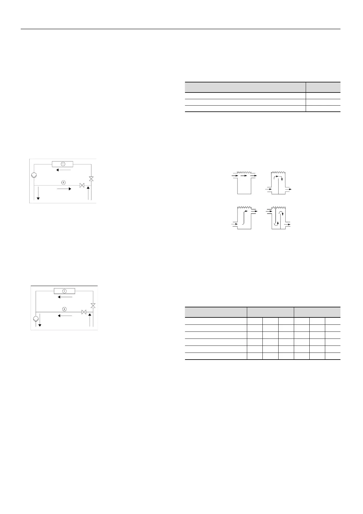
The tank must itself be internally baed in order to ensure proper
mixing of the liquid (water or brine). Refer to the examples below.
Connection to a buer tank
CorrectIncorrect
Incorrect Correct
7.6 - Maximum system water volume
Units with a hydraulic module may include an expansion vessel
which limits the volume in the water loop.
The table below gives the maximum loop volume compatible with
the expansion vessel (for pure water or ethylene glycol depending
on the system's various concentrations and static pressures).
If this volume is less than the volume of the installed loop, then it
is necessary to add an extra expansion vessel within the system.
30RB/RBP or 30RQ/RQP 165-270 310-950
Static pressure 1 2 2,5 1 2 2,5
Pure water 2400 1600 1200 3960 2640 1980
10% EG 1800 1200 900 2940 1960 1470
20% EG 1320 880 660 2100 1400 1050
30% EG 1080 720 540 1740 1160 870
40% EG 900 600 450 1500 1000 750
EG: Ethylene Glycol
7 - APPLICATION DATA
30

 Loading...