8.2 - Hydraulic connections
The hydraulic module options are only compatible with closed loops.
The use of the hydraulic module on open systems is prohibited.
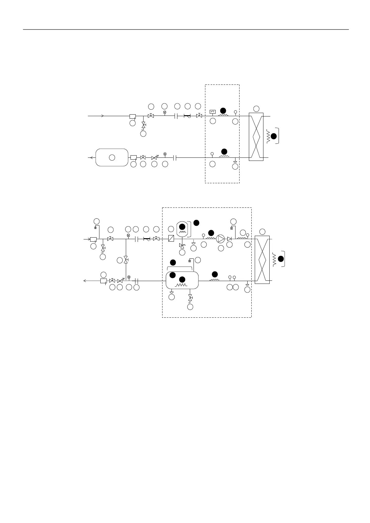
Typical hydraulic circuit diagram without the hydraulic module
12
9
8
6
2119
19
22
T
T
Op�on
23
Op�on
Op�on
21
14
25
16
16
13
13
13
20
19
18
Typical hydraulic circuit diagram with the hydraulic module
12
9
8
3
4
7
6
6
21
24
19
19
16
17
22
T
P
T
20
1
10
P
5
16
19
Op�on
11
23
13
Op�on
Op�on
Op�on
21
13
2
13
13
13
Op�on
6
5
23
25
25
13
15
18
18
Key
Components of the hydraulic module and the unit
1 Screen lter (particle size of 1.2 mm)
2 Expansion tank (option)
3 Relief valve
4 Circulating pump (single or dual)
5 Air vent
6 Water drain tap
7 Pressure sensor
Note: Provides pressure information for the pump inlet (see Control manual)
8 Temperature sensor
Note: Provides temperature information for the water exchanger outlet
(see Control manual)
9 Temperature sensor
Note: Provides temperature information for the water type heat exchanger inlet
(see Control manual)
10 Pressure sensor
Note: Provides pressure information for the water exchanger outlet (see Control
manual)
11 Check valve (If dual-pump)
12 Plate heat exchanger
13 Heater or heat trace cable for frost protection (Option)
14 Water type heat exchanger ow rate sensor
15 Water buer tank module (Option)
Installation components
16 Pocket
17 Air vent
18 Flexible connection
19 Shut-o valve
20 800 µm screen lter (mandatory for a unit without a hydraulic module)
21 Pressure gauge
22 Water ow control valve
Note: not required if hydraulic module with variable-speed pump
23 Charging valve
24 Bypass valve for frost protection (if shut-o valves are closed (item 19) during
winter)
25 Buer tank (if required)
---- Hydraulic module (unit with hydraulic module option)
Notes:
- The installation must be protected against freezing.
- The unit's hydraulic module and the water type heat exchanger may be protected
(factory-tted option) against freezing using electric heaters and heat trace
cables (13)
- The pressure sensors are assembled on connections without Schrader.
Depressurise and drain the system before any work.
8 - WATER CONNECTIONS
35

 Loading...