11
Step 6 — Position and Connect Controller —
Wired controllers should be installed in a position that
maintains good temperature control:
• Position the thermostat approximately 48 inches above
floor level.
• Do not position thermostat where it can be directly
affected by the unit’s discharge airstream.
• Avoid external walls and drafts from windows and doors.
• Avoid positioning near shelves and curtains as these
restrict air movement.
• Avoid heat sources such as direct sunlight, heaters,
dimmer switches, and other electrical devices
• See Fig. 15 for an example of communication wire
connection.
CONTROL WIRING
1. The communication wire should be 2-core stranded
shielded cable.
2. For IDU (indoor unit) and ODU (outdoor unit)
communication, use P, Q terminals. Shielded core should
be used for ground.
3. Wiring should be done according to wiring diagram.
4. Communication wire must not form a closed loop.
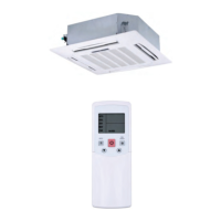
Fig. 15 —Communication Wire Connection
OPTION/EXTENSIONS OF COMMUNICATION
WIRING — To extend control wiring or make terminal
connections, use the PQE connection wire supplied in the
accessory kit and follow the steps below.
1. Cut the connector on the outdoor unit side as shown in
Fig. 16 below.
Fig. 16 —Shearing Outdoor Connector
2. Strip a suitable length of the insulation layer as shown in
Fig. 17 below.
Fig. 17 —Stripping the Wire
3. Use a suitable screwdriver to fix the communication wire
on the outdoor unit communication terminal as shown in
Fig. 18 below.
Fig. 18 —Connecting Communication Wire to
Outdoor Unit Communication Terminal
If communication wires are use to connect indoor units, find
the corresponding port and plug it directly as shown in Fig. 19.
Fig. 19 —Connecting the Communication Wires
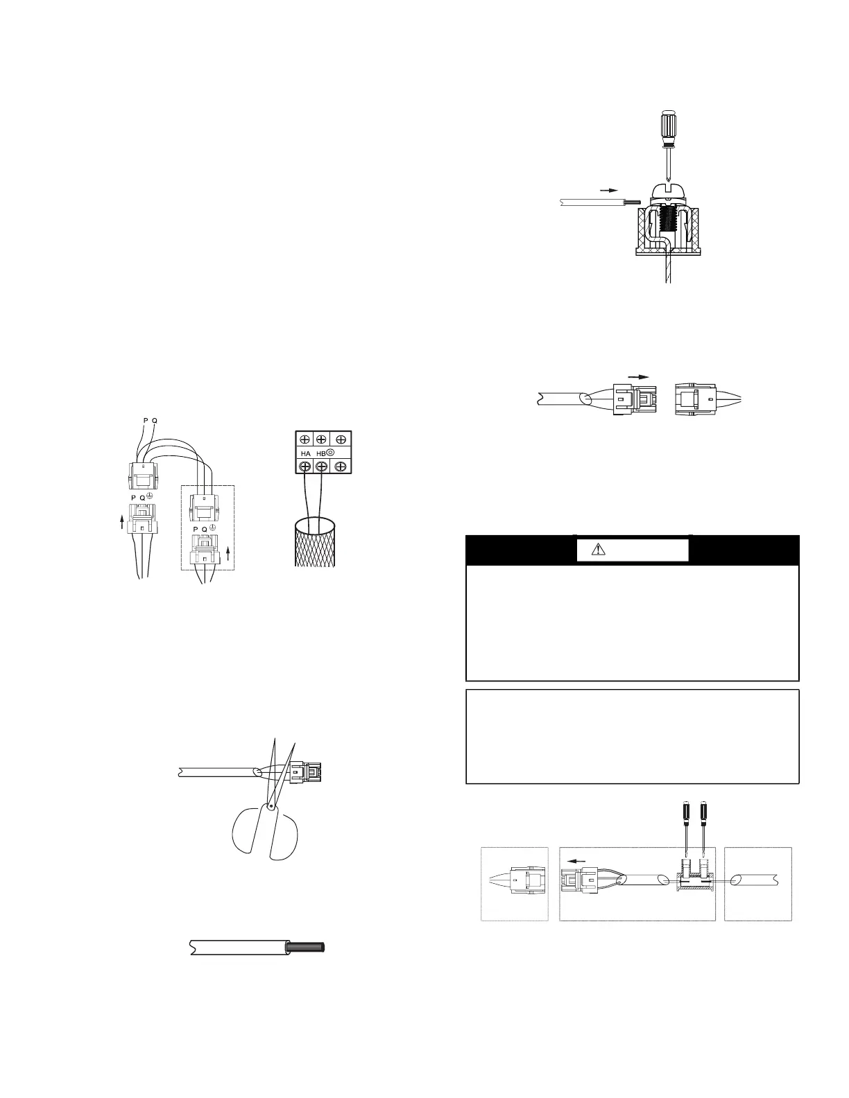
If it is not possible to buy communication wires from Carrier,
connect the indoor unit side of communication wires using the
connector provided with the accessories as shown in Fig. 20.
See Fig. 21 and 22 for typical communication wiring of the
heat pump and heat recovery systems.
To outdoor/indoor/MDC units
comm. bus
To wired controller comm. bus
XT2
CAUTION
Failure to follow these procedures may result in personal
injury or damage to equipment.
NEVER CONNECT the main power source to the control
or communication terminal block.
USE AN APPROPRIATE SCREWDRIVER for
tightening the terminal screws. Do not over tighten the
terminal screws.
IMPORTANT: Communication wiring shall be 2 inches
or more apart from power source wiring to avoid electric
noise. Do not insert control/communication and power
source wire in the same conduit.
Pay attention to polarity of the communication wire.
Connector in accessory kitConnector on indoor unit Communication cable
in field
Fig. 20 — Connecting the Communication Cable to
Indoor Unit to Outdoor Unit Using the Supplied
Connector

 Loading...