17
TROUBLESHOOTING
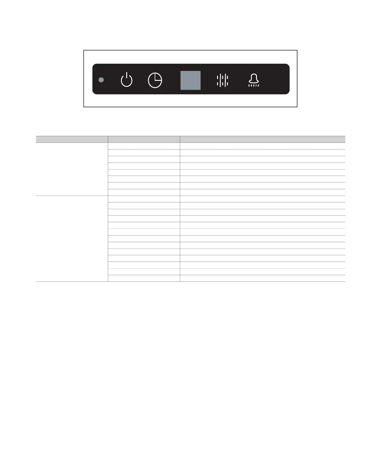
Fig. 29 shows the LED display panel on the indoor unit. See Table 6 for a summary of display indicators. Table 7 lists problems, possible
causes, and possible solutions.
Fig. 29 —LED Display Panel
Table 6 — Display Indicators
TYPE DIGITAL DISPLAY MODE/STATUS
[NO ERROR]
Setting Temperature Starting
“--” Shutdown
“--” Standby
“--” Timing ON
“--” Timing OFF
Setting Temperature System Defrost ON
Setting Temperature System Defrost OFF
Room Temperature Only Fan
ERROR
dd Heating / Cooling Mode Conflict Error
E1 Communication Error Between Indoor and Outdoor Unit
E2 Check Indoor Temperature Sensor (T1)
E4 Check Evaporator Outlet Temperature Sensor (T2B)
E5 Check Evaporator Temperature Sensor (T2A)
E6 Check DC Fan
E7 EEPROM Error (Data Storage)
E9 Communication Error Between Indoor Unit and Wired Controller.
Eb EEV Error
Ed Outdoor Unit Error
EE Condensate Overflow
FE No Address When Powered ON For First Time
UU MDC In Auto System-Check Mode.
LEGEND:
ACB — Auxiliary Control Board
EEPROM — Electronically Erasable Programmable Read-only Memory
EEV — Electronic Expansion Valve
MDC — Multiport Distribution Controller
A40-1716
OPERATION TIMER DEF./FAN ALARM
a40-1842

 Loading...