19
APPENDIX A — DIP SWITCH SETTINGS
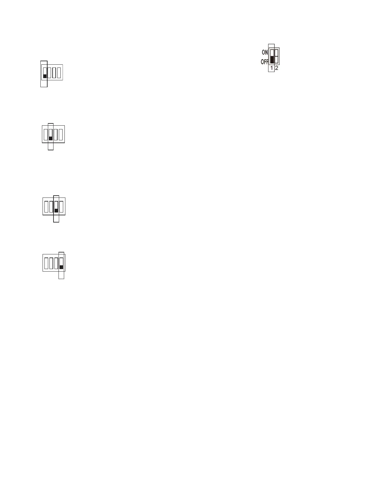
There are 2 DIP switches on the main board. Figures A and B
show the settings for each parameter controlled by a switch.
Switches are shown in the default settings.
POSITION 1 — START-UP
POSITION 2
POSITION 3 — NOT USED
POSITION 4 — INDOOR UNIT IDENTIFICATION
Fig. A — SW1 SETTINGS
Fig. B — SW8 SETTINGS
OFF — Auto Addressing Mode (Default)
ON — Factory Test Mode
OFF — Normal Mode (Default)
ON — Factory Self-Checking Mode
OFF — Standard Indoor Unit (Default)
ON — Mode Priority Indoor Unit (HP Only)
(IDU address must be 63)
OFF — Thermal off fan off
ON — Thermal Off Fan On
(The wired controller must be connected to
the indoor unit, and use the room
temperature sensor on the wired controller
to turn on this function)

 Loading...