8
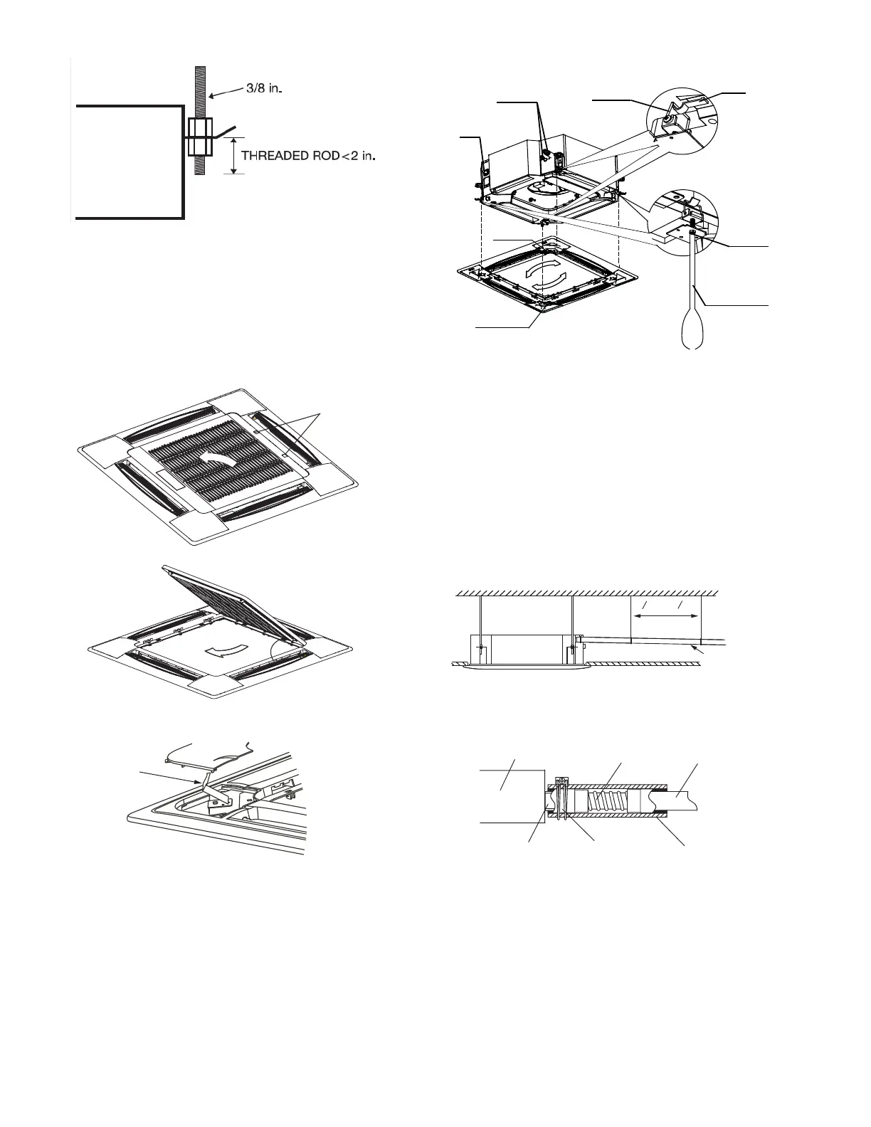
Fig. 8 —Threaded Rod
INSTALLING PANEL
NOTE: Panel is ordered separately.
1. Remove the grille from the panel by sliding the grille
latches toward the center of the panel.
2. Lift grille to a 45 angle and pull to detach it from panel.
3. Unscrew the bolts on the 4 corners of the cover panel.
Remove the cover by loosening the cord. See Fig. 9.
Fig. 9 —Removing Grille from Panel
4. Secure panel (without the grille) onto the unit using M5 x
16 screws and washers. Before tightening the screws, be
sure the panel is flush with the false ceiling. See Fig. 10.
Fig. 10 —Mounting Panel
5. When the panel is secure, insert the grille at a 45 angle
and latch it in place.
Step 4 — Connect Piping
CONDENSATE PIPING — The unit is supplied with a
1
-1
/
4
-inch OD drain connection to connect copper or plastic
drain piping. Follow these recommendations when installing
condensate piping:
• Maximum pump lift is 29
-1
/
2
inches.
• The highest point in the condensate piping should be as
close to the unit as possible. See Fig. 11-13 below.
Fig. 11 —Condensate Piping
Fig. 12 —Condensate Drain Connection
Louver motor
Louver
motor
Drainage
pipe joint
Hook
Panel hook
Piping joint
Hook bolt
Phillips
screwdriver
MIN. GRADIENT
2
5
8
TO 3
1
4
ft
INSULATION
INDOOR
UNIT
FLEXIBLE DRAIN
CONDENSATE HOSE CLAMP
CONNECTOR
PVC DRAIN
PIPE

 Loading...