11
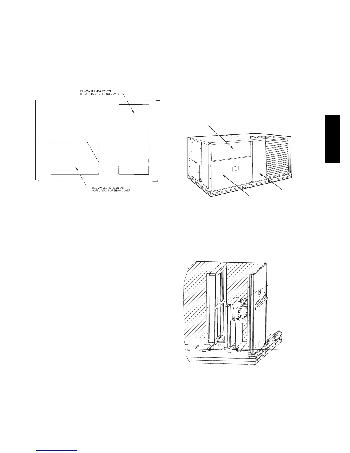
Step 7 — Convert to Horizontal and Connect
Ductwork (when required)
Unit is shipped in the vertical duct configuration. Unit
without factory--installed economizer or return air smoke
detector option may be field--converted to horizontal ducted
configuration. To convert to horizontal configuration,
remove screws from side duct opening covers and remove
covers. Using the same screws, install covers on vertical
duct openings with the insulation--side down. Seals around
duct openings must be tight. See Fig. 7.
C06108
Fig. 7 -- Horizontal Conversion Panels
Field--supplied flanges should be attached to horizontal
duct openings and all ductwork should be secured to the
flanges. Insulate and weatherproof all external ductwork,
joints, and roof or building openings with counter flashing
and mastic in accordance with applicable codes.
Do not cover or obscure visibility to the unit’s informative
data plate when insulating horizontal ductwork.
Step 8 — Install Outside Air Hood
Economizer Hood Package Removal and Setup --
Factory Option
1. The hood is shipped in knock--down form and must be
field assembled. The indoor coil access panel is used as
the hood top while the hood sides, divider and filter are
packaged together, attached to a metal support tray us-
ing plastic stretch wrap, and shipped in the return air
compartment behind the indoor coil access panel. The
hood assembly’s metal tray is attached to the basepan
and also attached to the damper using two plastic tie--
wraps.
2. To gain access to the hood, remove the filter access
panel. (See Fig. 8.)
FILTER ACCESS PANEL
OUTDOOR-AIR OPENING AND
INDOOR COILACCESS PANEL
COMPRESSOR
ACCESS PANEL
C06023
Fig. 8 -- Typical Access Panel Locations
3. Locate the (2) screws holding the metal tray to the
basepan and remove. Locate and cut the (2) plastic
tie--wraps securing the assembly to the damper. (See
Fig. 9) Be careful to not damage any wiring or cut
tie--wraps securing any wiring.
Hood Parts
Plastic Tie Wrap
Qty (2)
Screws for Metal Tray
Qty (2)
C08639
Fig. 9 -- Economizer Hood Parts Location
4. Carefully lift the hood assembly (with metal tray)
through the filter access opening and assemble per the
steps outlined in Economizer Hood, below.
48HC48LC

 Loading...


