23
Disconnect
per
NEC
13
L1 L2 L3
IFTB
C
208/230-3-60
460-3-60
575-3-60
Units Without Disconnect or HACR Option
Units With Disconnect or HACR Option
L1
L2
L3
2
4
6
1
5
Optional
Disconnect
Switch
Factory
Wiring
3
Ground
(GR)
Equip
GR Lug
Equip GR Lug
Ground
(GR)
3 Phase Only 3 Phase Only
C12148
Fig. 30 -- Power Wiring Connections
!
WARNING
FIRE HAZARD
Failure to follow this warning could result in
intermittent operation or performance satisfaction.
Do not connect aluminum wire between disconnect
switch and 48LC unit. Use only copper wire.
(See Fig. 31.)
COPPER
WIRE ONLY
ELECTRIC
DISCONNECT
SWITCH
ALUMINUM
WIRE
A93033
Fig. 31 -- Disconnect Switch and Unit
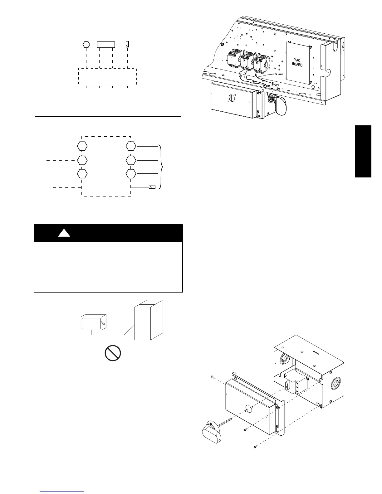
Units With Factory--Installed Non--Fused Disconnect or
HACR —
The factory--installed optional non--fused disconnect (NFD)
or HACR switch is located in a weatherproof enclosure
located under the main control box. The manual switch
handle and shaft is shipped in the disconnect or HACR
enclosure. Assemble the shaft and handle to the switch at
this point.
C12278
Fig. 32 -- Location of Non--Fused Disconnect Enclosure
To field install the NFD shaft and handle:
1. Remove the unit front panel (see Fig. 2).
2. Remove (3) hexagon screws on the front cover -- (2)
on the face of the cover and (1) on the left side cover.
3. Remove the front cover of the NFD enclosure.
4. Make sure the NFD shipped from the factory is at
OFF position (the arrow on the black handle knob is
at OFF).
5. Insert the shaft with the cross pin on the top of the
shaft in the horizontal position.
6. Measure from the tip of the shaft to the top surface of
the black pointer; the measurement should be 3.75 --
3.88 in. (95 -- 99 mm).
7. Tighten the locking screw to secure the shaft to the
NFD.
8. Turn the handle to the OFF position with red arrow
pointing at OFF.
9. Install the handle on to the painted cover horizontally
with the red arrow pointing to the left.
10. Secure the handle to the painted cover with (2) screws
and lock washers supplied.
11. Engaging the shaft into the handle socket, re--install
(3) hexagon screws on the front cover.
12. Re--install the unit front panel.
C12279
Fig. 33 -- Handle and Shaft Assembly for NFD
48HC48LC

 Loading...


