24
C12280
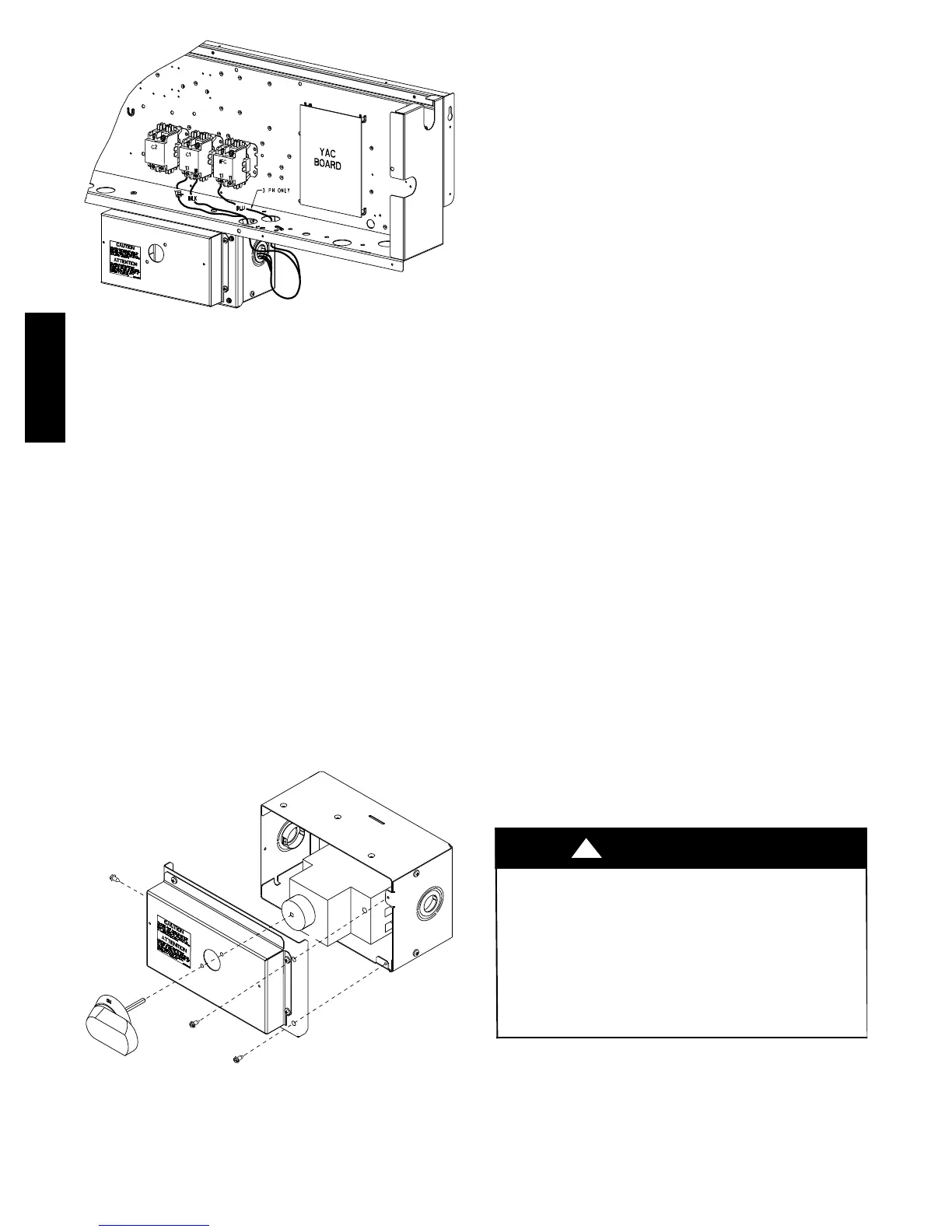
Fig. 34 -- Location of HACR Enclosure
To field install the HACR shaft and handle:
1. Remove the unit front panel (see Fig. 2).
2. Remove (3) hexagon screws on the front cover -- (2)
on the face of the cover and (1) on the left side cover.
3. Remove the front cover of the HACR enclosure.
4. Make sure the HACR shipped from the factory is at
OFF position (the white arrow pointing at OFF).
5. Insert the shaft all the way with the cross pin on the
top of the shaft in the horizontal position.
6. Tighten the locking screw to secure the shaft to the
HACR.
7. Turn the handle to the OFF position with red arrow
pointing at OFF.
8. Install the handle on to the painted cover horizontally
with the red arrow pointing to the left.
9. Secure the handle to the painted cover with (2) screws
and lock washers supplied.
10. Engaging the shaft into the handle socket, re--install
(3) hexagon screws on the front cover.
11. Re--install the unit front panel.
C12281
Fig. 35 -- Handle and Shaft Assembly for HACR
Units Without Factory--Installed Non--Fused Disconnect
or HACR —
When installing units, provide a disconnect switch per
NEC (National Electrical Code) of adequate size.
Disconnect sizing data is provided on the unit informative
plate. Locate on unit cabinet or within sight of the unit per
national or local codes. Do not cover unit informative
plate if mounting the disconnect on the unit cabinet.
All Units —
All field wiring must comply with NEC and all local
codes. Size wire based on MCA (Minimum Circuit Amps)
on the unit informative plate. See Fig. 30 and the unit
label diagram for power wiring connections to the unit
power terminal blocks and equipment ground. Maximum
wire size is #2ga AWG per pole on contactors. #2ga AWG
per pole on optional disconnect or HACR. See Fig. 30 and
unit label diagram for field power wiring connections.
Provide a ground--fault and short--circuit over--current
protection device (fuse or breaker) per NEC Article 440
(or local codes). Refer to unit informative data plate for
MOCP (Maximum Over--current Protection) device size.
NOTE: Units ordered with factory installed HACR do
not need an additional ground--fault and short--circuit
over--current protective device unless required by local
codes.
All field wiring must comply with the NEC and local
requirements.
All units except 208/230-v units are factory wired for the
voltage shown on the nameplate. If the 208/230-v unit is
to be connected to a 208-v power supply, the control
transformer must be rewired by moving the black wire
with the
1
/
4
-in. female spade connector from the 230--v
connection and moving it to the 200-v
1
/
4
-in. male
terminal on the primary side of the transformer. Refer to
unit label diagram for additional information.
NOTE: Check all factory and field electrical connections
for tightness.
Convenience Outlets —
ELECTRICAL OPERATION HAZARD
Failure to follow this warning could result in personal
injury or death.
Units with convenience outlet circuits may use multiple
disconnects. Check convenience outlet for power status
before opening unit for service. Locate its disconnect
switch, if appropriate, and switch to off position.
Lock--out and tag--out this switch, if necessary.
!
WARNING
Two types of convenience outlets are offered on 48LC
models: Non--powered and unit--powered. Both types
provide a 125--volt GFCI (ground--fault circuit--interrupter)
duplex receptacle rated at 15--A behind a hinged
waterproof access cover, located on the end panel of the
unit. See Fig. 36.
48HC48LC

 Loading...


