6
INSTALLATION
Jobsite Survey
Complete the following checks before installation.
1. Consult local building codes and the NEC (National
Electrical Code) ANSI/NFPA 70 for special installa-
tion requirements.
2. Determine unit location (from project plans) or select
unit location.
3. Check for possible overhead obstructions which may
interfere with unit lifting or rigging.
Step 1 — Plan for Unit Location
Select a location for the unit and its support system (curb
or other) that provides for the minimum clearances
required for safety. This includes the clearance to
combustible surfaces, unit performance and service access
below and around unit as specified in Fig. 3.
NOTE: Consider also the effect of adjacent units.
Be sure that unit is installed such that snow will not block
the combustion intake or flue outlet.
Unit may be installed directly on wood flooring or on
Class A, B, or C roof--covering material when roof curb is
used.
Do not install unit in an indoor location. Do not locate air
inlets near exhaust vents or other sources of contaminated
air. For proper unit operation, adequate combustion and
ventilation air must be provided in accordance with
Section 5.3 (Air for Combustion and Ventilation) of the
National Fuel Gas Code, ANSI Z223.1 (American
National Standards Institute) and NFPA (National Fire
Protection Association) 54 TIA----54----84----1. In Canada,
installation must be in accordance with the CAN1----B149
installation codes for gas burning appliances.
Although unit is weatherproof, avoid locations that permit
water from higher level runoff and overhangs to fall onto
the unit.
Locate mechanical draft system flue assembly at least 4 ft
(1.2 m) from any opening through which combustion
products could enter the building, and at least 4 ft (1.2 m)
from any adjacent building (or per local code). Locate the
flue assembly at least 10 ft (3.05 m) from an adjacent
unit’s fresh air intake hood if within 3 ft (0.91 m) of same
elevation (or per local code). When unit is located
adjacent to public walkways, flue assembly must be at
least 7 ft (2.1 m) above grade.
Select a unit mounting system that provides adequate
height to allow installation of condensate trap per
requirements. Refer to Step 11 — Install External
Condensate Trap and Line – for required trap dimensions.
Roof Mount —
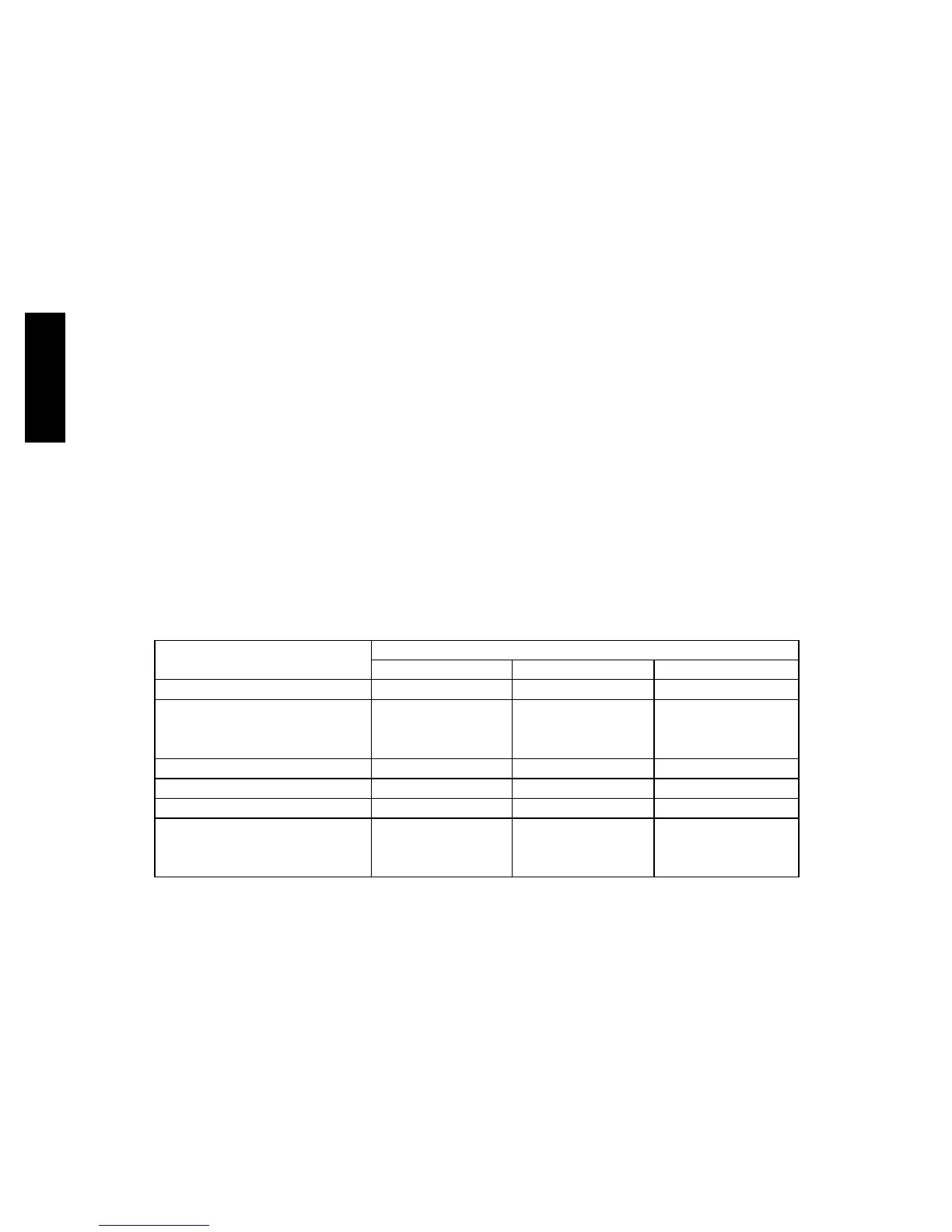
Check building codes for weight distribution
requirements. Unit operating weight is shown in Table 1.
Table 1 – Operating Weights
48LC**
UNITS LB (KG)
04 05 06
Base Unit 505 (229) 590 (268) 600 (272)
Economizer
Vertical 50 (23) 50 (23) 50 (23)
Horizontal 80 (36) 80 (36) 80 (36)
H u m i d i --- M i Z e r
R
System 50 (23) 55 (25) 55 (25)
Cu Fins 25 (11) 43 (20) 56 (25)
Powered Outlet 35 (16) 35 (16) 35 (16)
Curb
14---in/356 mm 115 (52) 115 (52) 115 (52)
24---in/610 mm 197 (89) 197 (89) 197 (89)
48HC48LC

 Loading...


