14
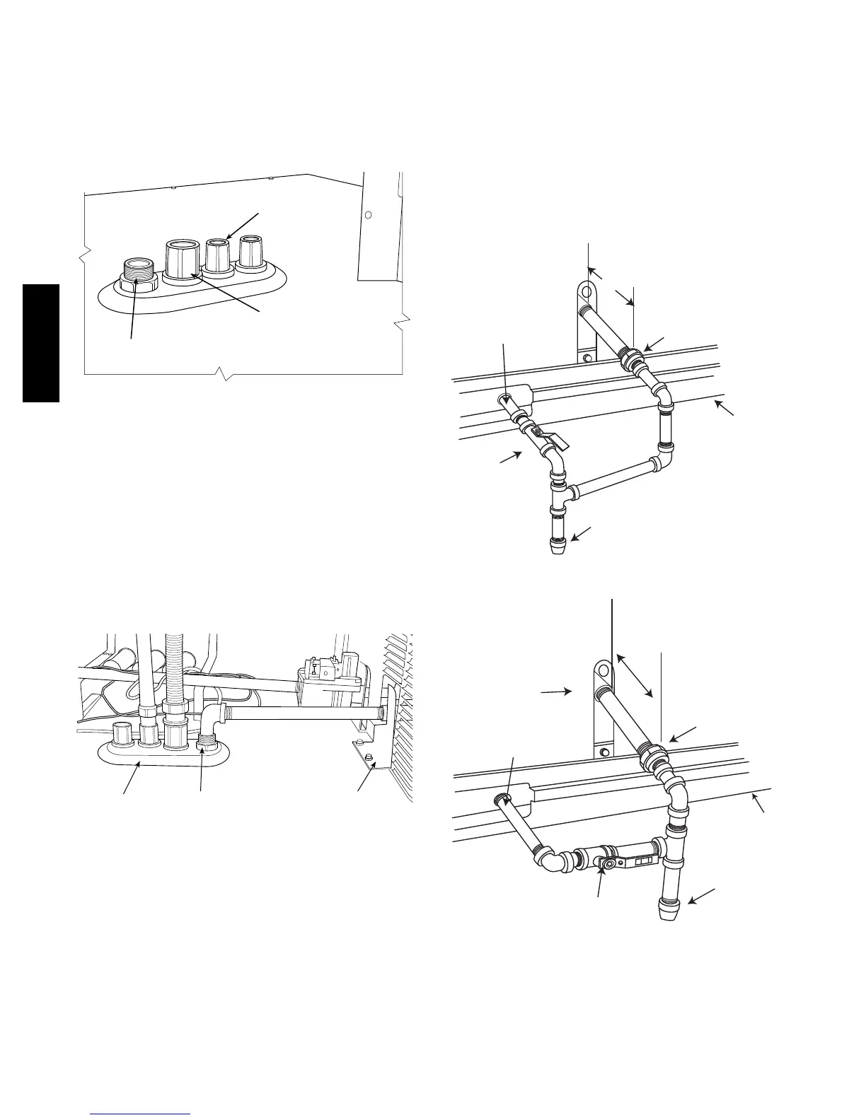
Factory--Option Thru--Base Connections
(Gas Connections)—
This service connection kit consists of a
1
/
2
-- i n N P T g a s
adapter fitting (brass), two
1
/
2
--in electrical bulkhead
connectors and a
3
/
4
--in electrical bulkhead connector, all
factory--installed in the embossed (raised) section of the
unit basepan in the condenser section.
LOW VOLTAGE
CONDUIT
CONNECTOR
HIGH VOLTAGE
CONDUIT
CONNECTOR
BRASS FITTING FOR 3 TO 6 TON UNITS.
C13410
Fig. 16 -- Fittings
The thru--base gas connector has male and female threads.
The male threads protrude above the basepan of the unit;
the female threads protrude below the basepan.
Check tightness of connector lock nuts before connecting
gas piping.
Install a
1
/
2
--in NPT street elbow on the thru--base gas
fitting. Attach a
1
/
2
--in pipe nipple with minimum length
of 16--in (406 mm) (field--supplied) to the street elbow
and extend it through the access panel at the gas support
bracket. See Fig. 17.
EMBOSSMENT
BRASS FITTING
FOR 3-6 TON UNITS
SUPPORT
BRACKET
C13411
Fig. 17 -- Gas Line Piping for 3 to 5 Ton Units Only
Other hardware required to complete the installation of the
gas supply line will include a manual shutoff valve, a
sediment trap (drip leg) and a ground--joint union. A
pressure regulator valve may also be required (to convert gas
pressure from pounds to inches of pressure). The manual
shutoff valve must be located within 6--ft (1.83 m) of the
unit. The union, located in the final leg entering the unit,
must be located at least 9--in (230 mm) away from the
access panel to permit the panel to be removed for service.
If a regulator valve is installed, it must be located a
minimum of 4--ft (1220 mm) away from the unit’s flue
outlet. Some municipal codes require that the manual shutoff
valve be located upstream of the sediment trap. See Figures
18 and 19 for typical piping arrangements for gas piping that
has been routed through the sidewall of the curb. See Fig. 20
for typical piping arrangement when thru--base is used.
Ensure that all piping does not block access to the unit’s
main control box or limit the required working space in front
of the control box.
9” (229mm) min
Union
Shut Off
Valve
Drip
Leg
Thru-Curb Adapter
Unit Base Rail
C07469
Fig. 18 -- Gas Piping
Drip
Leg
Shut Off
Valve
Union
Thru-Curb Adapter
Burner
Access
Panel
9” (229mm) min
Unit Base Rail
C07470
Fig. 19 -- Gas Piping
48HC48LC

 Loading...


