5
ABBREVIATIONS AND EXPLANATIONS
Frequently used abbreviations in this manual include:
Words printed in all capital letters or in italics may be
viewed on the International Chiller Visual Controller (ICVC)
(e.g., LOCAL, CCN, ALARM, etc.).
Words printed in both all capital letters and italics can also
be viewed on the ICVC and are parameters (e.g., CONTROL
MODE, COMPRESSOR START RELAY, ICE BUILD
OPTION, etc.) with associated values (e.g., modes, tempera-
tures, percentages, pressures, on, off, etc.).
Words printed in all capital letters and in a box represent
softkeys on the ICVC control panel (e.g., , ,
, , etc.).
Factory-installed additional components are referred to as
options in this manual; factory-supplied but field-installed
additional components are referred to as accessories.
The chiller software part number of the 19XRV unit is
located on the back of the ICVC.
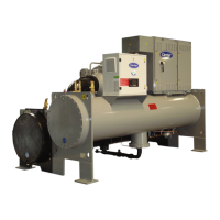
CHILLER FAMILIARIZATION
(FIG. 1-3)
Chiller Information Nameplate —
The information
nameplate is located on the right side of the chiller control
panel.
System Components — The components include the
cooler and condenser heat exchangers in separate vessels,
compressor-motor, lubrication package, control panel, econo-
mizer (optional) and VFD. All connections from pressure ves-
sels have external threads to enable each component to be pres-
sure tested with a threaded pipe cap during factory assembly.
Cooler — This vessel (also known as the evaporator) is
located underneath the compressor. The cooler is maintained at
lower temperature/pressure so evaporating refrigerant can
remove heat from water flowing through its internal tubes.
Condenser — The condenser operates at a higher
temperature/pressure than the cooler and has water flowing
through its internal tubes in order to remove heat from the
refrigerant.
Motor-Compressor — This component maintains sys-
tem temperature and pressure differences and moves the heat-
carrying refrigerant from the cooler to the condenser. Compres-
sor Frames 2-5 are single-stage compressors with one impeller.
Frame E compressors are two-stage compressors with two im-
pellers.
Economizer (Optional) — The economizer is a sepa-
rate vessel in the flow path after the condenser that improves
the refrigerant cycle by allowing a small amount of refrigerant
to flash into vapor. This phase change decreases the tempera-
ture of the remaining liquid refrigerant. The vapor is drawn into
the second stage of the compressor, which saves energy be-
cause the refrigerant does not have to be compressed by both
stages.
Control Panel — The control panel is the user interface
for controlling the chiller. It regulates the chiller’s capacity as
required to maintain proper leaving chilled water temperature.
The control panel:
• registers cooler, condenser, and lubricating system pressures
• shows the chiller operating condition and the alarm
shutdown conditions
• records the total chiller operating hours
• sequences chiller start, stop, and recycle under microproces-
sor control
• displays the status of the VFD
• provides access to other CCN (Carrier Comfort Network
®
)
devices and energy management systems
• languages pre-installed at factory include: English, Chinese,
Japanese, and Korean.
• International Language Translator (ILT) is available for
conversion of extended ASCII characters.
Variable Frequency Drive (VFD) — The VFD al-
lows for the proper start and disconnect of electrical energy for
the compressor-motor, oil pump, oil heater, and control panel.
Storage Vessel (Optional) — There are 2 sizes of
storage vessels available. The vessels have double relief valves,
a magnetically-coupled dial-type refrigerant level gage, a
one-inch FPT drain valve, and a
1
/
2
-in. male flare vapor con-
nection for the pumpout unit.
NOTE: If a storage vessel is not used at the jobsite, factory-
installed isolation valves on the chiller may be used to isolate
the chiller charge in either the cooler or condenser. An optional
pumpout system is used to transfer refrigerant from vessel to
vessel.
CAUTION
This unit uses a microprocessor control system. Do not
short or jumper between terminations on circuit boards or
modules; control or board failure may result.
Be aware of electrostatic discharge (static electricity) when
handling or making contact with circuit boards or module
connections. Always touch a chassis (grounded) part to
dissipate body electrostatic charge before working inside
control center.
Use extreme care when handling tools near boards and
when connecting or disconnecting terminal plugs. Circuit
boards can easily be damaged. Always hold boards by the
edges and avoid touching components and connections.
This equipment uses, and can radiate, radio frequency
energy. If not installed and used in accordance with the
instruction manual, it may cause interference to radio
communications. It has been tested and found to comply
with the limits for a Class A computing device pursuant to
International Standard in North America EN61000-2/3
which are designed to provide reasonable protection
against such interference when operated in a commercial
environment. Operation of this equipment in a residential
area is likely to cause interference, in which case the user,
at his own expense, will be required to take whatever mea-
sures may be required to correct the interference.
Always store and transport replacement or defective boards
in anti-static shipping bag.
CCM — Chiller Control Module
CCN — Carrier Comfort Network
®
CCW — Counterclockwise
CW — Clockwise
ECDW — Entering Condenser Water
ECW — Entering Chilled Water
EMS — Energy Management System
HGBP — Hot Gas Bypass
I/O — Input/Output
ICVC — International Chiller Visual Controller
LCD — Liquid Crystal Display
LCDW — Leaving Condenser Water
LCW — Leaving Chilled Water
LED — Light-Emitting Diode
OLTA — Overload Trip Amps
PIC III — Product Integrated Controls III
RLA — Rated Load Amps
SI — International System of Units
SRD — Split Ring Diffuser
TXV — Thermostatic Expansion Valve
UPC — Universal Protocol Card
VFD — Variable Frequency Drive