71
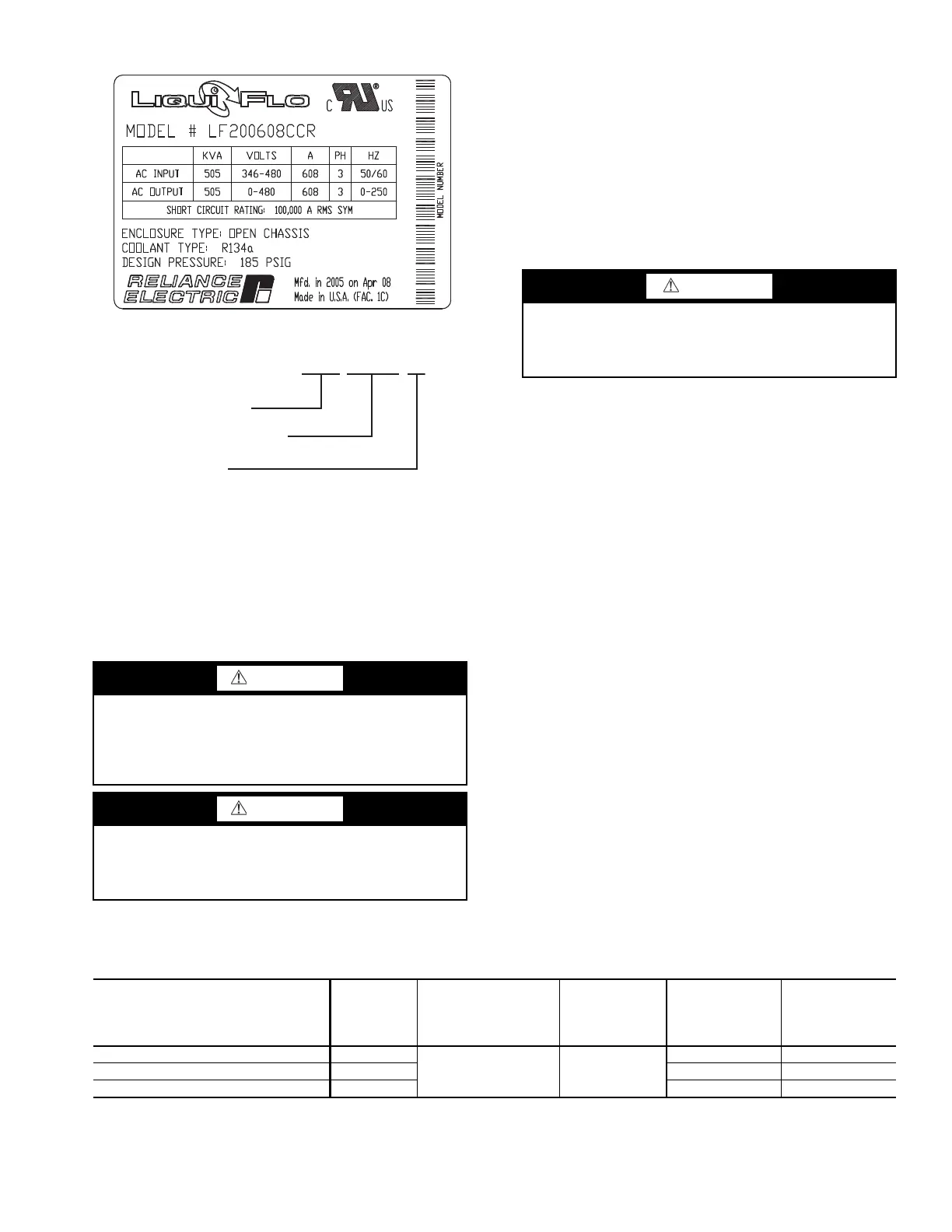
IDENTIFYING THE DRIVE BY PART NUMBER — Each
AC drive can be identified by its assembly number. See
Fig. 38. This number appears on the shipping label and on the
drive nameplate. LiquiFlo™ 2.0 AC power module can be
identified by its model number. See Fig. 39. This number
appears on the shipping label and on the power module’s
nameplate. Power ratings are provided in Table 12.
Input Power Wiring — All wiring should be installed in
conformance with applicable local, national, and international
codes. Use grommets, when hubs are not provided, to guard
against wire chafing.
Use the following steps to connect AC input power to the
main input circuit breaker:
1. Turn off, lockout, and tag the input power to the drive.
2. Remove the input wiring panel and drill the required
number of openings in the top of the drive enclosure.
Take care that metal chips do not enter the enclosure.
3. Wire the AC input power leads by routing them through
the openings to the main input circuit breaker.
4. Connect the three-phase AC input power leads (per job
specification) to the appropriate input terminals of the
circuit breaker.
5. Tighten the AC input power terminals to the proper
torque as specified on the input circuit breaker.
Checking the Installation — Use the following in-
structions to verify the condition of the installation:
1. Turn off, lockout, and tag the input power to the drive.
2. Wait a minimum of 5 minutes for the DC bus to discharge.
3. All wiring should be installed in conformance with the
applicable local, national, and international codes (e.g.,
NEC/CEC).
4. Remove any debris, such as metal shavings, from the
enclosure.
5. Check that there is adequate clearance around the
machine.
6. Verify that the wiring to the terminal strip and the power
terminals is correct.
7. Verify that all of the VFD power module circuit board
connectors are fully engaged and taped in place.
8. Check that the wire size is within terminal specifications
and that the wires are tightened properly.
9. Check that specified branch circuit protection is installed
and correctly rated.
10. Check that the incoming power is within ± 10% of chiller
nameplate voltage.
11. Verify that a properly sized ground wire is installed and a
suitable earth ground is used. Check for and eliminate any
grounds between the power leads. Verify that all ground
leads are unbroken.
Table 12 — Drive Assembly and Power Module Ratings
*110% output current capability for 1 minute. 150% output current capability for 5 sec.
WARNING
BE AWARE that certain automatic start arrangements can
engage the VFD. Open the disconnect ahead of the VFD in
addition to shutting off the chiller or pump. Failure to do so
could result in serious personal injury or death from elec-
tric shock.
WARNING
The main disconnect on the VFD front panel may not de-
energize all internal circuits. Open all internal and remote
disconnects before servicing the VFD. Failure to do so could
result in serious personal injury or death from electric shock.
Fig. 38 — VFD Nameplate
a19-1723
LF20
LF20 = LiquiFlo 2.0
Continuous Ampere Rating
and Frame Size
0608CC
Coolant Method
R = refrigerant R134a
R
Fig. 39 — Identifying the Drive Model Number
a19-1629
CAUTION
Do not route control wiring carrying 30 v or less within a
conduit carrying 50 v or higher. Failure to observe this
precaution could result in electromagnetic interference in
the control wiring.
PART NUMBER
FRAME
SIZE
ENCLOSURE
RATING
NAMEPLATE
INPUT
VOLTAGE
(V)
MAX
INPUT
CURRENT
(AMPS)
MAX
OUTPUT
CURRENT
AT 4 KHZ*
(AMPS)
19XVA2AA__________ 2AA
NEMA 1
380 TO
460
442 442
19XVA2CC__________ 2CC 608 608
19XVA4CC__________ 4CC 1169 1169
 Loading...