93
TROUBLESHOOTING GUIDE
(TABLES 15-18B)
Overview —
The PIC III has many features to help the
operator and technician troubleshoot a 19XRV chiller.
• The ICVC shows the chiller’s actual operating conditions
and can be viewed while the unit is running.
• The ICVC default screen freezes when an alarm occurs. The
freeze enables the operator to view the chiller conditions at
the time of alarm. The STATUS screens continue to show
current information. Once all alarms have been cleared (by
correcting the problems and pressing the softkey),
the ICVC default screen returns to normal operation.
• The CONTROL ALGORITHM STATUS screens (which
include the CAPACITY, OVERRIDE, LL_MAINT,
VFD_HIST, LOADSHED, CUR_ALARM, WSM-
DEFME, and OCCDEFCM screens) display information
that helps to diagnose problems with chilled water tempera-
ture control, chilled water temperature control overrides, hot
gas bypass, surge algorithm status, and time schedule opera-
tion. See Table 15.
• The control test feature facilitates the proper operation and
test of temperature sensors, pressure transducers, the guide
vane actuator, oil pump, water pumps, tower control, and
other on/off outputs while the compressor is stopped. It also
has the ability to lock off the compressor and turn on water
pumps for pumpout operation. The ICVC shows the tem-
peratures and pressures required during these operations.
• From other SERVICE tables, the operator/technician can
access configured items, such as chilled water resets, over-
ride set points, etc.
• If an operating fault is detected, an alarm message is gener-
ated and displayed on the ICVC default screen. A more
detailed message — along with a diagnostic message — is
also stored into the ALARM HISTORY and ALERT HIS-
TORY tables.
• Review the ALERT HISTORY table to view other less crit-
ical events and abnormal conditions which may have
occurred. Compare timing of relevant alerts and alarms.
Checking Display Messages — The first area to
check when troubleshooting the 19XRV is the ICVC display. If
the alarm light is flashing, check the primary and secondary
message lines on the ICVC default screen (Fig. 18). These
messages will indicate where the fault is occurring. These
messages contain the alarm message with a specified code. For
a complete list of possible alarm and alert messages, see
Table 16. This code or state appears with each alarm and alert
message. The ALARM and ALERT HISTORY tables on the
ICVC SERVICE menu also contains a message to further
expand on the fault description. For a complete list of VFD
Fault Code Descriptions and corrective actions, see Table 17.
NOTE: The date format in these tables is MM/DD/YY.
If the alarm light starts to flash while accessing a menu
screen, press the softkey to return to the default screen
to read the alarm message. The STATUS screen can also be ac-
cessed to determine where an alarm exists.
A “C” to the right of a parameter’s value means that there is
a communications fault on that channel.
Checking Temperature Sensors — All tempera-
ture sensors are thermistor-type sensors. This means that the
resistance of the sensor varies with temperature. All sensors
have the same resistance characteristics. If the controls are on,
determine sensor temperature by measuring voltage drop; if the
controls are powered off, determine sensor temperature by
measuring resistance. Compare the readings to the values listed
in Table 18A or 18B.
RESISTANCE CHECK — Turn off the control power and,
from the module, disconnect the terminal plug of the sensor in
question. With a digital ohmmeter, measure sensor resistance
between receptacles as designated by the wiring diagram. The
resistance and corresponding temperature are listed in
Table 18A or 18B. Check the resistance of both wires to
ground. This resistance should be infinite.
VOLTAGE DROP — The voltage drop across any energized
sensor can be measured with a digital voltmeter while the
control is energized. Table 18A or 18B lists the relationship
between temperature and sensor voltage drop (volts dc
measured across the energized sensor). Exercise care when
measuring voltage to prevent damage to the sensor leads,
connector plugs, and modules. Sensors should also be checked
at the sensor plugs. Check the sensor wire at the sensor for
5 vdc if the control is powered on.
CHECK SENSOR ACCURACY — Place the sensor in a
medium of known temperature and compare that temperature
to the measured reading. The thermometer used to determine
the temperature of the medium should be of laboratory quality
with 0.5 F (.25 C) graduations. The sensor in question should
be accurate to within 2 F (1.2 C).
See Fig. 12 for sensor locations. The sensors are immersed
directly in the refrigerant or water circuits. The wiring at each
sensor is easily disconnected by unlatching the connector.
These connectors allow only one-way connection to the sensor.
When installing a new sensor, apply a pipe sealant or thread
sealant to the sensor threads.
DUAL TEMPERATURE SENSORS — For servicing con-
venience, there are 2 sensors each on the bearing and motor
temperature sensors. If one of the sensors is damaged, the other
can be used by simply moving a wire. The number 2 terminal
in the sensor terminal box is the common line. To use the
second sensor, move the wire from the number 1 position to the
number 3 position.
Checking Pressure Transducers — There are 6
factory-installed pressure transducers, with inputs available for
optional cooler and condenser waterside differential pressure
transducers. The ICVC software will display a default reading
of 26 psi during start-up and operation. An additional transduc-
er, factory installed in the bottom of the cooler barrel, will read
as EVAPORATOR SATURATION TEMP on the HEAT_EX
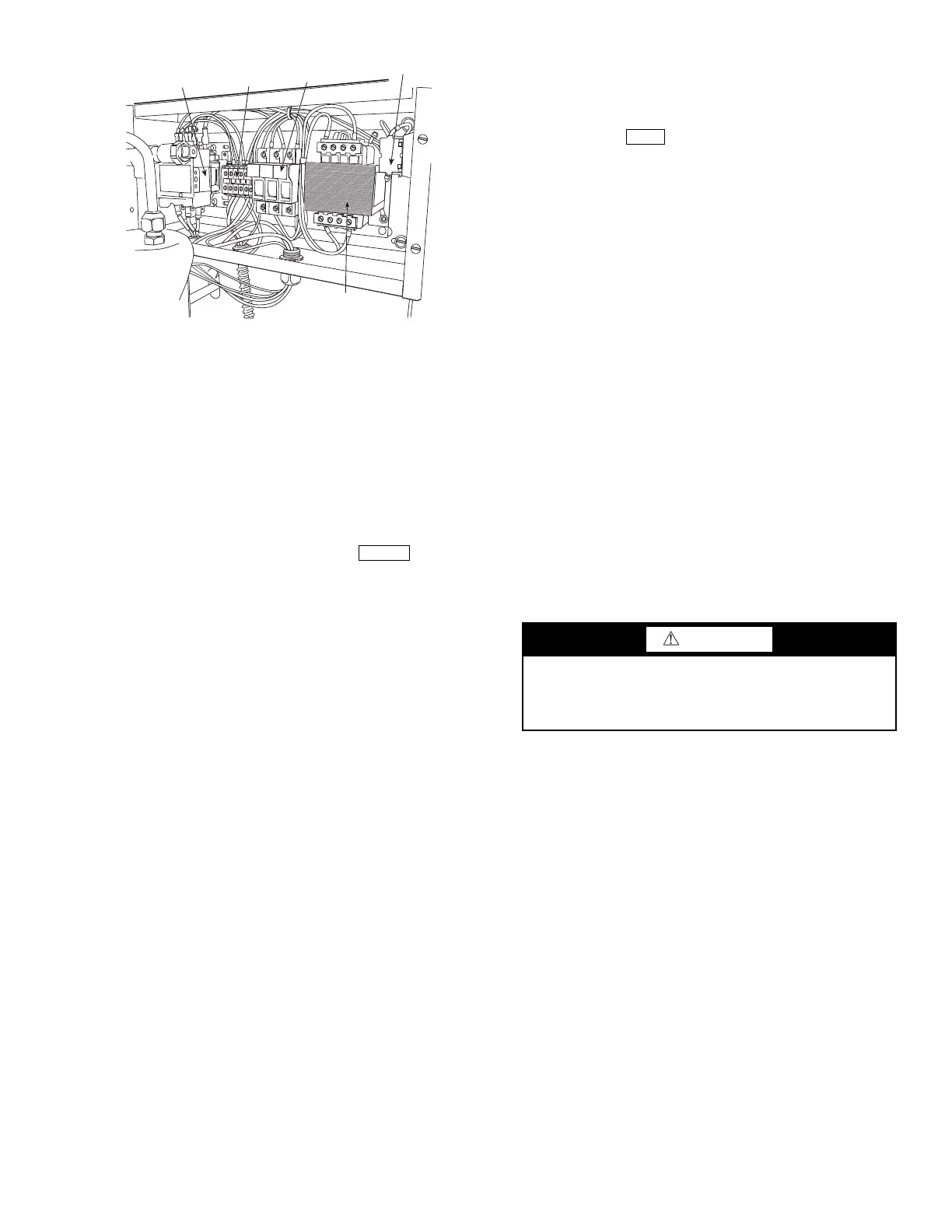
CONTACTOR
TERMINAL
STRIP
FUSES
TRANSFORMER
SWITCH
Fig. 54 — Pumpout Control Box (Interior)
a19-1569
CAUTION
Relieve all refrigerant pressure or drain the water before
replacing temperature sensors or thermowells threaded into
the refrigerant pressure boundary. Failure to do so could
result in personal injury and equipment damage.
 Loading...