74
Table 13 — Job Site Parameters
*With variable flow systems this point may be configured to the lower
end of the range.
NOTE: Other parameters: Screens are normally left at the default
settings; they may be changed by the operator as required. The time
and persistence settings on the VFD_CONF table can be adjusted
to increase or decrease the sensitivity to a fault condition. Increasing
time or persistence decreases sensitivity. Decreasing time or per-
sistence increases sensitivity to the fault.
INPUT EQUIPMENT SERVICE PARAMETERS IF NEC-
ESSARY — The EQUIPMENT SERVICE table has six
service tables.
VERIFY VFD CONFIGURATION AND CHANGE
PARAMETERS IF NECESSARY (Fig. 40)
VFD CHILLER FIELD SET UP AND VERIFICATION
Label Locations
— Verify that the following labels have been
installed properly and match the chiller requisition:
• Surge Parameters — Located inside the control panel. See
Fig. 14.
• Refrigeration Machine Nameplate — Located on the right
side of the control panel. See Fig. 14.
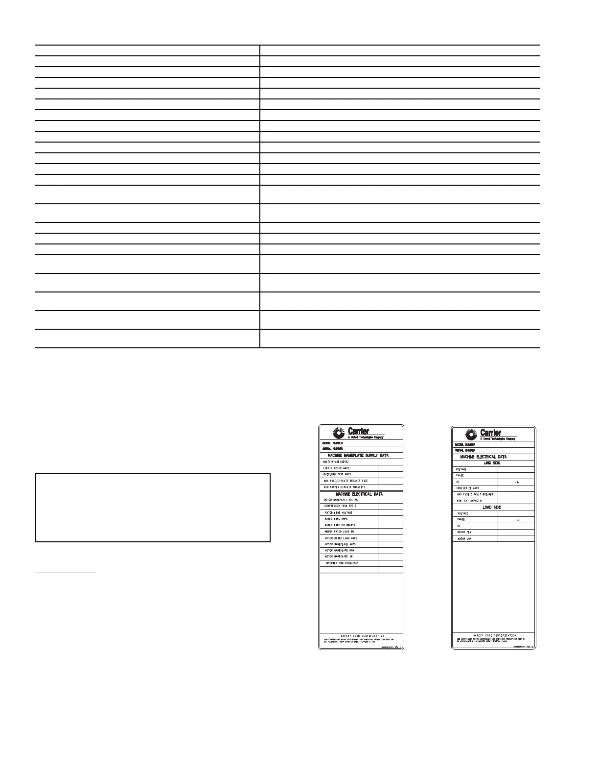
• External Machine Electrical Data Nameplate — Located on
the right side of the VFD as viewed from its front. See
Fig. 40.
• Internal Machine Electrical Data Nameplate — Located on
the inside of the left VFD enclosure door. See Fig. 40.
• Record all nameplate information on the Initial Start-up
Checklist at the end of this manual.
PARAMETER TABLE
Motor Nameplate Voltage VFD_CONF - from chiller information nameplate
Compressor 100% Speed VFD_CONF - from chiller information nameplate
Line Freq=60 Hz? (No=50) VFD_CONF - from chiller information nameplate
Rated Line Voltage VFD_CONF - from chiller information nameplate
Rated Line Amps VFD_CONF - from chiller information nameplate
Rated Line Kilowatts VFD_CONF - from chiller information nameplate
Motor Rated Load KW VFD_CONF - from chiller information nameplate
Motor Rated Load Amps VFD_CONF - from chiller information nameplate
Motor Nameplate Amps VFD_CONF - from chiller information nameplate
Motor Nameplate RPM VFD_CONF - from chiller information nameplate
Motor Nameplate KW VFD_CONF - from chiller information nameplate
Surge Limit/HGBP Option OPTIONS - Enter 1 or 2 if HGBP is installed. Enter 0 otherwise.
Minimum Load Points (Tsmin, IGVmin) OPTIONS - Per Chiller Requisition (Tsmin, IGVmin) per job data - See Modify
Load Points section. Refer to table located in the control panel.
FULL (Maximum) load points (TsMax, IGVmax) OPTIONS - Per Chiller Requisition (Tsmax, IGVmax) per job data - See Modify
Load Points section. Refer to table located in the control panel.
Surge Line Shape Factor OPTIONS - Per Chiller Requisition. Refer to table located in the control panel.
Chilled Medium SETUP1 - Enter Water or Brine
Evaporator Refrigerant trippoint SETUP1 - Usually 3 F (1.7 C) below design refrigerant temperature
*Evaporator Flow Delta P cutout SETUP1 - Per Chiller Requisition if available or enter 50% of design pressure
drop
Condenser Flow Delta P cutout SETUP1 - Per Chiller Requisition if available or enter 50% of design pressure
drop
High Condenser Water Delta P Enter the maximum value for the condenser water pressure drop if chiller is
connected to a condenser water manifold system. Otherwise leave at default.
Diffuser Option (compressors with Split Ring Diffusers) SETUP2 - ENABLE for 4 and 5 frame compressors with Split Ring Diffusers.
See table in control panel for values.
Diffuser Full Span mA (Compressors with Split Ring
Diffusers)
SETUP2 - Enter diffuser actuator full span mA value for 4 and 5 frame compres-
sors with Split Ring Diffusers. See label on side of diffuser actuator for values.
IMPORTANT: The VFD controller has been factory config-
ured for use and communications to the International Chiller
Visual Controller (ICVC). Some parameters are specific to
the chiller configuration and will need to be verified prior to
operation. All command functions must be initiated from
the ICVC.
Fig. 40 — Machine Electrical Data Nameplate
INTERNAL EXTERNAL
a19-1626
 Loading...