60
If the module number is not valid, the “COMMUNICA-
TION FAILURE” message will show and a new address
number must be entered or the wiring checked. If the module is
communicating properly, the “UPLOAD IN PROGRESS”
message will flash and the new module can now be viewed.
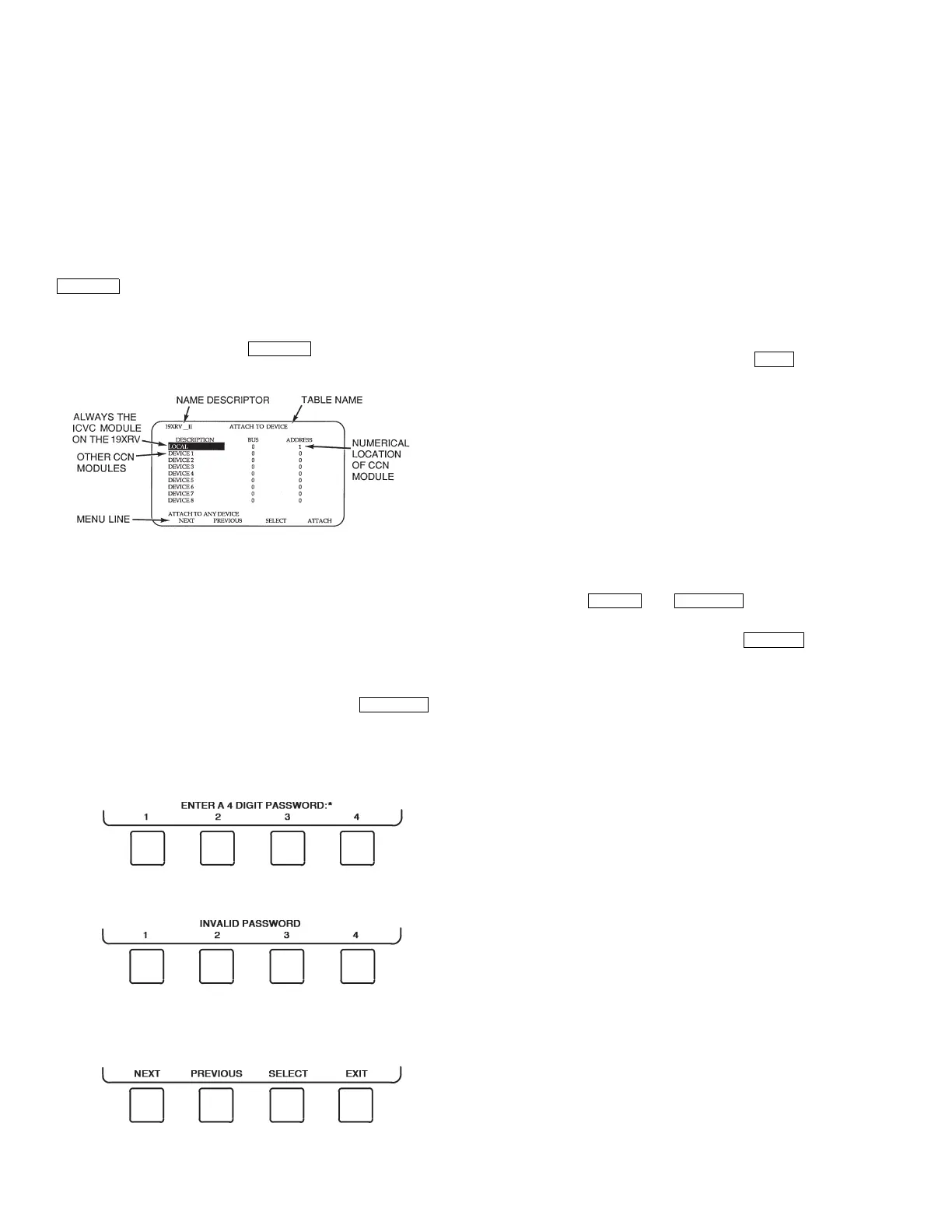
Whenever there is a question regarding which module on
the ICVC is currently being shown, check the device name
descriptor on the upper left hand corner of the ICVC screen.
See Fig. 30.
When the CCN device has been viewed, the ATTACH TO
NETWORK DEVICE table should be used to attach to the PIC
that is on the chiller. Move to the ATTACH TO NETWORK
DEVICE table (LOCAL should be highlighted) and press the
softkey to upload the LOCAL device. The ICVC
for the 19XRV will be uploaded and default screen will display.
NOTE: The ICVC will not automatically reattach to the local
module on the chiller. Press the softkey to attach to
the LOCAL device and view the chiller operation.
Service Operation — An overview of the tables and
screens available for the SERVICE function is shown in
Fig. 21.
TO ACCESS THE SERVICE SCREENS — When the
SERVICE screens are accessed, a password must be entered.
1. From the main MENU screen, press the
softkey. The softkeys now correspond to the numerals 1,
2, 3, 4.
2. Press the four digits of the password, one at a time. An as-
terisk (*) appears as each digit is entered.
NOTE: The initial factory-set password is 1-1-1-1. If the
password is incorrect, an error message is displayed.
If this occurs, return to Step 1 and try to access the
SERVICE screens again. If the password is correct, the
softkey labels change to:
NOTE: The SERVICE screen password can be changed by
entering the ICVC CONFIGURATION screen under SER-
VICE menu. The password is located at the bottom of the
menu.
The ICVC screen displays the following list of available
SERVICE screens:
•Alarm History
•Alert History
• Control Test
• Control Algorithm Status
• Equipment Configuration
• VFD Config Data
• Equipment Service
• Time and Date
• Attach to Network Device
• Log Out of Device
• ICVC Configuration
See Fig. 21 for additional screens and tables available from
the SERVICE screens listed above. Use the softkey to
return to the main MENU screen.
NOTE: To prevent unauthorized persons from accessing the
ICVC service screens, the ICVC automatically signs off and
password-protects itself if a key has not been pressed for
15 minutes. The sequence is as follows. Fifteen minutes after
the last key is pressed, the default screen displays, the ICVC
screen light goes out (analogous to a screen saver), and the
ICVC logs out of the password-protected SERVICE menu.
Other screen and menus, such as the STATUS screen can be
accessed without the password by pressing the appropriate
softkey.
TO LOG OUT OF NETWORK DEVICE — To access this
screen and log out of a network device, from the default ICVC
screen, press the and softkeys. Enter the
password and, from the SERVICE menu, highlight LOG OUT
OF NETWORK DEVICE and press the softkey.
The ICVC default screen will now be displayed.
TIME BROADCAST ENABLE — The first displayed line,
“Time Broadcast Enable,” in the SERVICE/EQUIPMENT
CONFIGURATION/BRODEF screen, is used to designate the
local chiller as the sole time broadcaster on a CCN network
(there may only be one). If there is no CCN network present
and/or there is no designated time broadcaster on the network,
current time and date, Daylight Saving Time (DST), and holi-
days as configured in the local chiller’s control will be applied.
If a network is present and one time broadcaster on the network
has been enabled, current time and date, DST, and holiday
schedules as configured in the controls of the designated time
broadcaster will be applied to all CCN devices (including
chillers) on the network.
HOLIDAY SCHEDULING (FIG. 31) — Up to 18 different
holidays can be defined for special schedule consideration.
There are two different screens to be configured.
First, in the SERVICE/EQUIPMENT CONFIGURATION/
HOLIDAYS screen, select the first unused holiday entry
(HOLDY01S, for example). As shown in Fig. 26, enter a num-
ber for Start Month (1 = January, 2 = February, …, 12 = Decem-
ber), a number for Start Day (1 - 31), and Duration in days (0 -
99). By default there are no holidays set up. Second, in the occu-
pancy Schedule tables, specify and enable (by setting “X” under
the “H” column) run time period(s) which will apply to all holi-
days. (Refer to Fig. 23.) A run time period which is enabled for
holidays may be applied to one or more non-holiday days of the
week as well. This may be done for the local (table OC-
CPC01S), Ice Build (OCCPC02S), and/or CCN (OCCPC03S)
schedule(s). If the chiller is on a CCN network, the active holi-
day definition will be that configured in the device designated at
Fig. 30 — Example of Attach to Network
Device Screen
a19-1743
 Loading...