IMPORTANT: The damper blade on factory-supplied vent damper has a 1/2-sq in. hole (approximately 3/4-in. diameter). On boilers equipped
with standing pilot, the hole MUST be left open. On boilers equipped with intermittent ignition, the hole should be plugged using plug supplied
with vent damper.
1. Position factory-supplied vent damper on top of flue outlet collar. Fasten damper securely to flue outlet collar with at least 2 sheet metal
screws. Make sure damper blade has clearance to operate inside of diverter.
As An Option:
The damper may be installed in any horizontal or vertical position, closer to flue outlet collar preferred. Follow diagrams shown in Fig. 8,
9, and 10.
2. Install vent damper to service only single boiler for which it is intended. The damper position indicator shall be in a visible location
following installation. Locate damper so that it is accessible for servicing.
3. The damper must be in open position when appliance main burners are operating.
4. The boiler is equipped with a factory-wired harness that plugs into vent damper. The thermostat must be connected to black wires marked
"24 volt thermostat" on boiler.
5. Vent pipe must be same size as flue outlet collar.
6. Slope pipe up from boiler to chimney not less than 1/4 in. per ft.
7. Run pipe as directly as possible with as few elbows as possible.
8. Do not connect to fireplace flue.
9. End of vent pipe must be flush with inside face of chimney flue. Use a sealed-in thimble for chimney connection.
10. Horizontal run should not be longer than 3/4 the chimney height (HT). (See Fig. 7.)
The sections of vent pipe should be fastened with at least 3 sheet metal screws to make the piping rigid. Horizontal portions of vent system must
be supported to prevent sagging. Use stovepipe wires every 5 ft to support pipe from above. If vent pipe must go through a crawlspace, double-wall
vent pipe should be used. Where vent pipe passes through a combustible wall or partition, use a ventilated metal thimble. The thimble should be
4 in. larger in diameter than vent pipe.
PROCEDURE 4—MINIMUM VENT PIPE CLEARANCE
Wood and other combustible materials must not be closer than 6 in. from any surface of single-wall metal vent pipe. Listed Type-B vent pipe or
other listed venting systems shall be installed in accordance with their listing.
PROCEDURE 5—REMOVING EXISTING BOILER FROM COMMON VENTING SYSTEM
When an existing boiler is removed from a common venting system, the common venting system is likely to be too large for proper venting of
the appliances remaining connected to it.
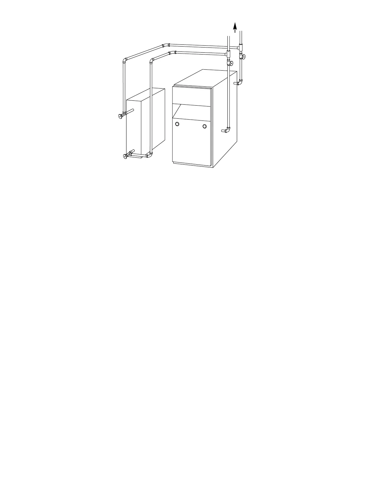
Fig. 6—Chilled Water Piping
A95143
VALVES A & B
OPEN FOR HEATING;
CLOSE FOR COOLING
TO SYSTEM
A
B
C
D
WATER
CHILLER
VALVES C & D
CLOSE FOR HEATING;
OPEN FOR COOLING
—10—

 Loading...