14. For pumped return systems, follow condensate pump or boiler feed pump manufacturer’s instructions for proper installation and hookup.
15. In connecting cold water supply to water inlet valve, make sure that a clean water supply is available. When water supply is from a well
or pump, a sand strainer should be installed at pump.
PROCEDURE 1—FOR USE WITH COOLING UNITS
1. This boiler, when used in connection with chilled water systems, must be installed so that chilled water is piped in parallel with the heating
boiler. Appropriate valves must be used to prevent chilled water from entering the heating boiler. (See Fig. 6.)
2. When this boiler is connected to heating coils located in air handling units where they may be exposed to refrigerated air circulation, piping
system shall be equipped with flow control valves or other automatic means to prevent gravity circulation of boiler water during cooling
cycles.
CHIMNEY AND VENT PIPE CONNECTION
For boilers connected to gas vents or chimneys, vent installations shall be in accordance with Part 7 NFGC, Venting of Equipment and applicable
provisions of local building codes.
PROCEDURE 1—CHECKING CHIMNEY
This is a very important part of the heating system. It must be clean, the right size, properly constructed, and in GOOD CONDITION. No boiler
can function properly with a bad chimney. Inspect chimney and verify that construction and size of chimney meet all applicable provisions of the
NFGC and local building codes. Fig. 7 gives an idea how a boiler might be vented to a chimney. Note that height (HT) is measured from vent
pipe to top.
PROCEDURE 2—CHIMNEY SIZING
Chimney sizing and all other aspects of vent installation must be in accordance with Part 7, NFGC Venting of Equipment and applicable provisions
of local building codes.
PROCEDURE 3—CONNECTING VENT DAMPER AND VENT CONNECTOR
Refer to Fig. 1 flue diagram for size and location of vent (flue opening). Use 28 gauge (minimum) galvanized pipe to connect to chimney.
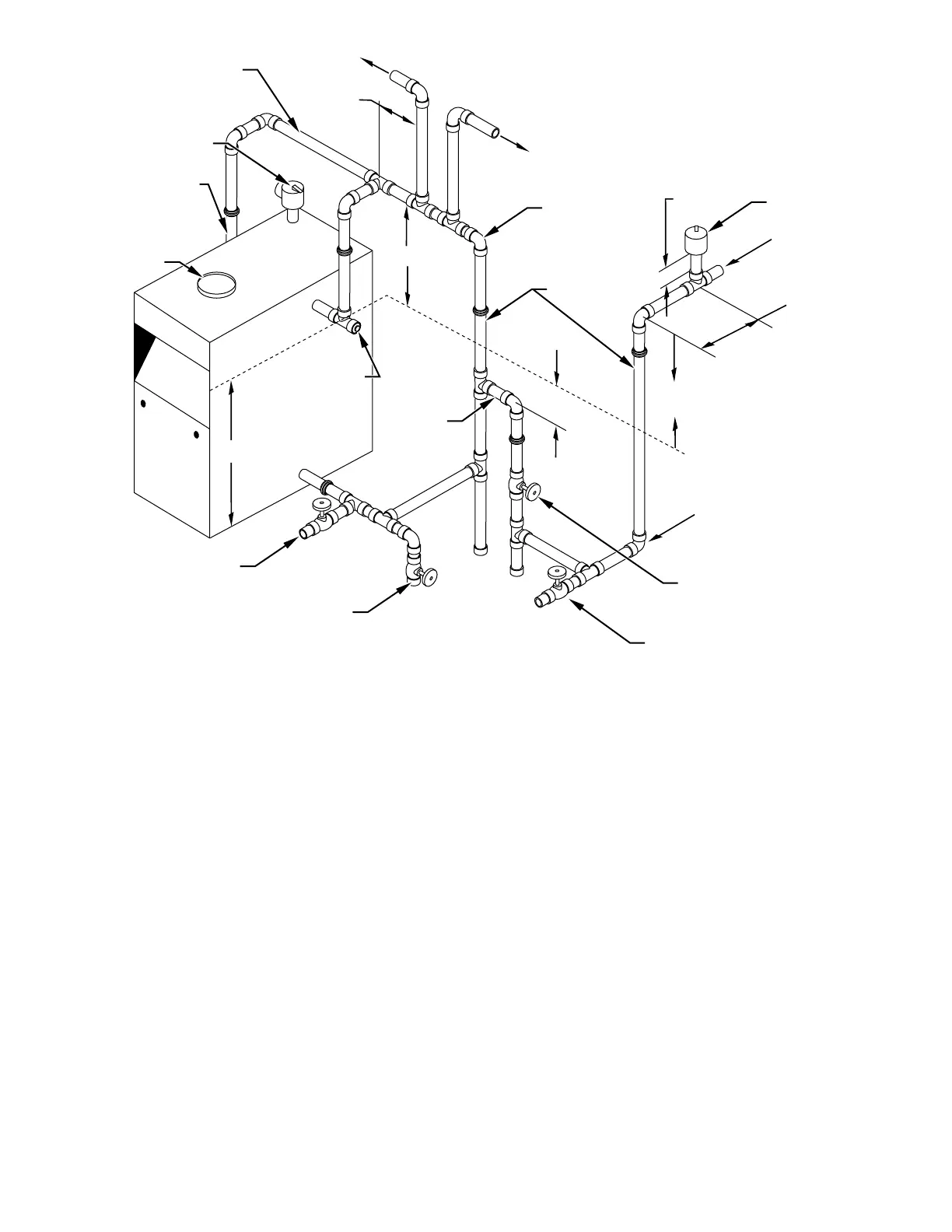
Fig. 4—Recommended Near Boiler Piping Using 2 Supply Tappings
A95494
PIPE FULL SIZE SAME
AS BOILER TAPPING
(2 1/2")
FLUE COLLAR
POP SAFETY VALVE
STEAM
MAINS
MAIN VENT
REDUCING ELL
POINTING DOWN
WATER FEED
GATE VALVE
(NOT FURNISED)
DRY
RETURN MAIN
WET RETURN
DRAIN VALVE (FURNISHED)
FOR FLUSHING SYSTEM
CLOSE
NIPPLE
15″ MIN.
6″
28″ MIN. - DIMENSION A
15″ MIN.
6″ TO 10″
24″ MIN.
1
1
/2″ MIN.
PIPE SIZE
1
1
/2″ FULL PORT BALL VALVE
FOR BOTTOM BLOW DOWN
AND DRAINING BOILER &
SYSTEM (NOT FURNISHED)
WATER LINE
24″
2
1
/2″ TEE
WITH PLUG
FOR SKIMMING
CONNECT RISER TO
BOILER WITH 2
1
/2″
ELBOW AND NIPPLE
(NOT SHOWN)
—8—

 Loading...