4. Allow boiler to fill until water runs out gauge drain valve, then close gauge drain valve.
5. Continue to fill boiler until water reaches indicated water line. This is about halfway up glass tube.
PROCEDURE 3—WATER LEVEL
The normal water level is shown on right side of boiler and is 24 in. above the floor. The normal water level is determined when boiler is off and
cold (when all of the water in system is inside boiler and return piping below water line) and everything above water line is air, no steam. When
boiler is making steam, the water level drops 2-3 in. below normal water line.
PROCEDURE 4—AUTOMATIC GAS VALVE
The automatic gas valve opens or closes according to heat requirements of thermostat and pressure limit control. It closes if pilot goes out. Each
individual control must be operating correctly before any gas can pass to burners. Any 1 control can hold gas supply from burners regardless of
demand of any other control.
PROCEDURE 5—THERMOSTAT
Keep thermostat set at desired room temperature. If windows are to be opened or heat is not needed, set thermostat to a lower setting.
NOTE: In the event of failure of any component, system will not operate or will go into safety lockout. The system is completely self-checking.
On every call for heat, each component must be functioning properly to permit operation. On safety lockout, system has to be reset by setting
thermostat to lowest setting for 1 minute, then back to normal setting.
Safe lighting and other performance criteria were met with gas manifold and control assembly provided on boiler when boiler underwent tests
specified in ANSI Z21.13.
CHECKING AND ADJUSTING
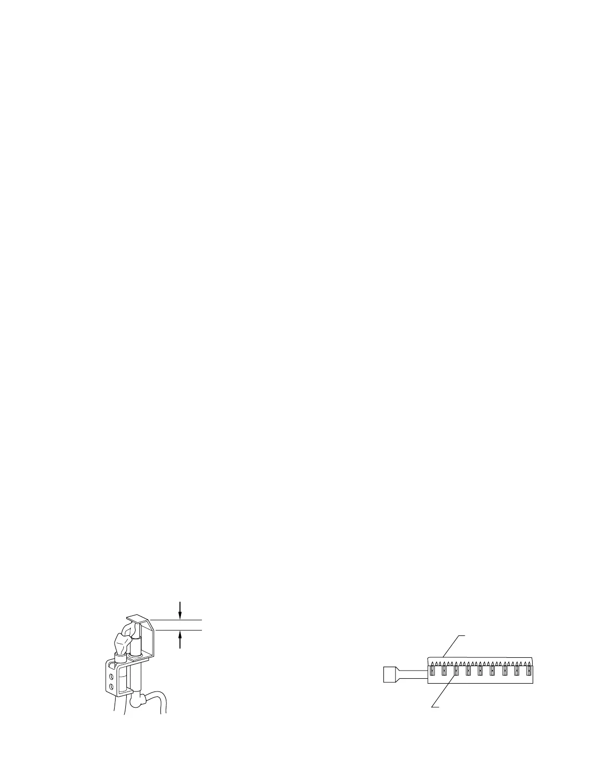
PROCEDURE 1—PILOT BURNER ADJUSTMENT
Pilot flame should surround 3/8- to 1/2-in. of pilot sensor. (See Fig. 21.) If flame needs adjusting, proceed as follows:
1. Remove screw cover over pilot adjusting screw.
2. Insert small screwdriver and adjust flame as needed. Turn screw counterclockwise to increase flame and clockwise to decrease flame.
3. Replace screw cover over pilot adjusting screw.
PROCEDURE 2—MAIN BURNER(S)
The main burners do not require primary air adjustment and are not equipped with primary air shutters. Main burner flames should form sharp
blue inner cones in a softer blue out mantel, with no yellow. Puffs of air from blowing on the flame or stamping on the floor will cause the flames
to turn orange momentarily. This is not unusual. Remain still when observing the main burner flames. If the flame appearance is not correct, check
main burner orifices and the burner throat and flame ports for dust and lint obstruction. It may be necessary to remove the rollout shield to observe
the main burner flames. Replace rollout shield after observation. (See Fig. 22.)
PROCEDURE 3—GAS VALVE SAFETY SHUTDOWN TEST
A. Boilers Equipped with Continuous Pilot
With main burners firing, disconnect thermocouple from gas valve. (See Fig. 19.) Gas valve should immediately shut off main burners and pilot.
B. Boilers Equipped with Intermittent Ignition
With main burners firing, disconnect ignition cable from intermittent pilot control box. Gas valve should shut off main burners. TURN OFF
ELECTRIC POWER to boiler before reconnecting ignition cable to prevent electric shock.
PROCEDURE 4—STEAM PRESSURE CONTROL ADJUSTMENT
The steam pressure limit control (pressuretrol) shuts off gas to main burners when steam pressure in boiler reaches cut-off setpoint (the sum of
cut-in and differential set points). Burners refire when steam pressure drops to cut-in setpoint. System pressure requirements are based on size and
condition of pipes and load.
For good system operation, the cut-in setting of pressuretrol should never be less than twice the system pressure drop. In a typical single family
residence with a clean 1-pipe heating system and cast iron radiation, this means that cut-in will usually be set at the minimum setting of 0.5 psi.
Steam radiation is usually sized based on sq ft of equivalent direct radiation (EDR). This is based on a steam pressure in radiator of just less than
1 psi. Therefore, in example system from above, the differential adjustment would be set at 1 psi (the steam pressure required in radiators). This
gives a cut-off setpoint of 1.5 psi.
Fig. 21—Pilot Flame and Sensor
A95160
3
⁄8″ to
1
⁄2″
FLAME
ON SENSOR
Fig. 22—Main Burner Flame
A99182
OUTER MANTEL
SHARP INNER CONES
—22—

 Loading...