The boiler and its individual shutoff valve must be disconnected from gas supply piping system during any pressure testing of gas supply piping
system at test pressures in excess of 0.5 psig (3.5 kPa).
The boiler must be isolated from gas supply piping system by closing its individual manual shutoff valve during any pressure testing of the gas
supply piping system at test pressures equal to or less than 0.5 psig (3.5 kPa).
PROCEDURE 2—CONNECTING GAS PIPING
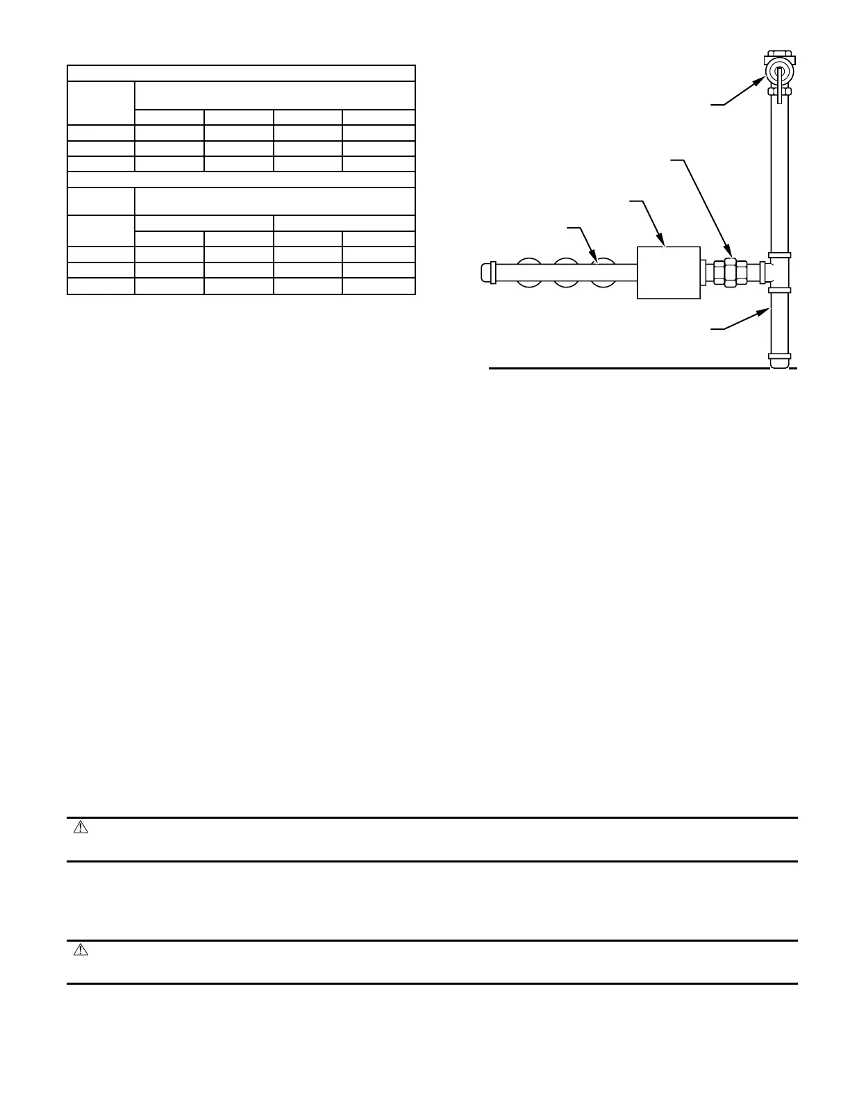
Refer to Fig. 11 for general layout at boiler. It shows the basic fittings needed. The gas line enters boiler from right side.
The following rules apply:
1. Use only those piping materials and joining methods listed as acceptable by the authority having jurisdiction or in the absence of such
requirements, by the NFGC.
2. Use pipe joint compound suitable for LP gas on male threads only.
3. Use ground joint unions.
4. Install a sediment trap upstream of gas controls.
5. Use 2 pipe wrenches when making connection to gas valve to keep it from turning.
6. Install a manual shutoff valve in vertical pipe about 5 ft above floor.
7. Tighten all joints securely.
8. Propane gas connections should only be made be a licensed propane installer.
9. Two-stage regulation should be used by propane installer.
10. Propane gas piping should be checked by propane installer.
PROCEDURE 3—CHECKING GAS PIPING
Upon completion of piping, check immediately for gas leaks. Open manual shutoff valve. Test for leaks by applying soap suds (or a liquid
detergent) to each joint. Bubbles forming indicate a leak. CORRECT EVEN THE SMALLEST LEAK AT ONCE.
WARNING:
Never use a match or open flame to test for leaks. Use a soap-and-water solution. A failure to follow this
warning could result in fire, explosion, personal injury, or death.
ELECTRICAL WIRING
See Fig. 12-15 for wiring diagrams of the various models.
PROCEDURE 1—ELECTRIC POWER SUPPLY
WARNING: Turn off electric power at fuse box before making any line voltage connections. Follow local electric
codes. Failure to follow this warning could result in electrical shock, personal injury, or death.
All electrical work must conform to local codes as well as the National Electrical Code (NEC) ANSI/NFPA-70-2002.
Run a separate 120-v circuit from a separate overcurrent protective device in electrical service entrance panel. This should be a 15-amp circuit.
Locate a shutoff switch at boiler. It must be turned off during any maintenance. Connect 120-v electrical supply to primary leads on 24-v
transformer. Solder and tape or securely fasten these connections with wire nuts.
Table 4—Gas Pipe Sizes
NATURAL GAS
Length
of Pipe
(Ft)
Pipe Capacity—Btuh Input
Includes Fittings
1/2 in. 3/4 in. 1 in. 1-1/4 in.
20 92,000 190,000 350,000 625,000
40 63,000 130,000 245,000 445,000
60 50,000 105,000 195,000 365,000
LP GAS
Length
of Pipe
Pipe Capacity—Btuh Input
Includes Fittings
(Ft)
Copper Tubing* Iron Pipe
5/8 in. 3/4 in. 1/2 in. 3/4 in.
20 131,000 216,000 189,000 393,000
40 90,000 145,000 129,000 267,000
60 72,000 121,000 103,000 217,000
* Outside diameter.
NOTE: The length of pipe or tubing shown should be measured from gas meter or
propane second-stage regulator.
Fig. 11—Gas Piping at Boiler
A95148
MANIFOLD
AUTOMATIC
GAS VALVE
MANUAL
SHUTOFF
VALVE
SEDIMENT TRAP
FLOOR LINE
GROUND JOINT
UNION
—13—

 Loading...