24
115-V
FIELD-SUPPLIED
DISCONNECT
SWITCH
115-V
SINGLE
PHASE
AUXILIARY
J-BOX
FURNACE
CONTROL
CENTER
TWO WIRE
24-V
TERMINAL
BLOCK
THREE-WIRE
HEATING
ONLY
FIVE
WIRE
NOTE 5
NOTE 1
NOTE
3
THERMOSTAT
TERMINALS
FIELD-SUPPLIED
DISCONNECT
CONDENSING
UNIT
R
W2
WCR GY
GND
GND
GND
GND
FIELD 24-V WIRING
FIELD 115-, 208/230-, 460-V WIRING
FACTORY 24-V WIRING
FACTORY 115-, 208/230-, 460-V WIRING
208/230- OR
460-V
THREE PHASE
208/230-V
SINGLE
PHASE
W/W1
Y/Y2
G
C
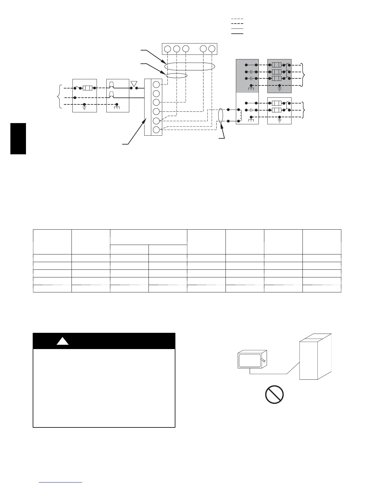
NOTES:
1.
2.
3.
4.
5.
Connect Y or Y/Y2 terminal as shown for proper cooling operation.
Proper polarity must be maintained for 115-v wiring.
Use W2 with 2-stage thermostat when zoning.
If any of the original wire, as supplied, must be replaced, use
same type or equivalent wire.
Some thermostats require a "C" terminal connection as shown.
A98325
Fig. 29 -- Heating and Cooling Application Wiring Diagram
Table 4 – Electrical Data
UNIT SIZE
V O LT S ---
H E R T Z ---
PHASE
OPERATING VOLTAGE
RANGE
MAXIMUM
UNIT
AMPS
MINIMUM
WIRE SIZE
MAXIMUM
WIRE
LENGTH}
MAXIMUM
FUSE OR C KT
BKR
AMPS**
Maximum* Minimum*
060---14 1 1 5 --- 6 0 --- 1 127 104 8.96 14 30 ft. / 9.1 m 15
080---14 1 1 5 --- 6 0 --- 1 127 104 8.96 14 30 ft. / 9.1 m 15
080---20 1 1 5 --- 6 0 --- 1 127 104 14.06 12 31 ft. / 9.4 m 20
100---20 1 1 5 --- 6 0 --- 1 127 104 14.06 12 31 ft. / 9.4 m 20
120---20 1 1 5 --- 6 0 --- 1 127 104 14.06 12 31 ft. / 9.4 m 20
* Permissible limits of voltage range at which unit will operate satisfactorily.
{ Unit ampacity = 125 percent of l argest operating component’s full load amps plus 100 percent of all other potential operating components’ (E AC,
humidifier, etc.) full load amps.
} Length shown is as measured 1 way along wire path between unit and service panel for maximum 2 percent voltage drop.
** Time---dela y type is r ecommended.
ELECTRICAL SHOCK AND FIRE HAZARD
Failure to follow this warning could result in electrical
shock, fire, or death.
The cabinet MUST have an uninterrupted or unbroken
ground according to NEC ANSI/NFPA 70--2005 and
Canadian Electrical Code CSA C22.1 or local codes to
minimize personal injury if an electrical fault should occur.
This may consist of electrical wire or conduit approved for
electrical ground when installed in accordance with existing
electrical codes. Do not use gas piping as an electrical
ground.
!
WARNING
COPPER
WIRE ONLY
ELECTRIC
DISCONNECT
SWITCH
ALUMINUM
WIRE
A93033
Fig. 30 -- Disconnect Switch and Furnac58Factory Installed
J--Box Location
58MVC
 Loading...