46
A99118
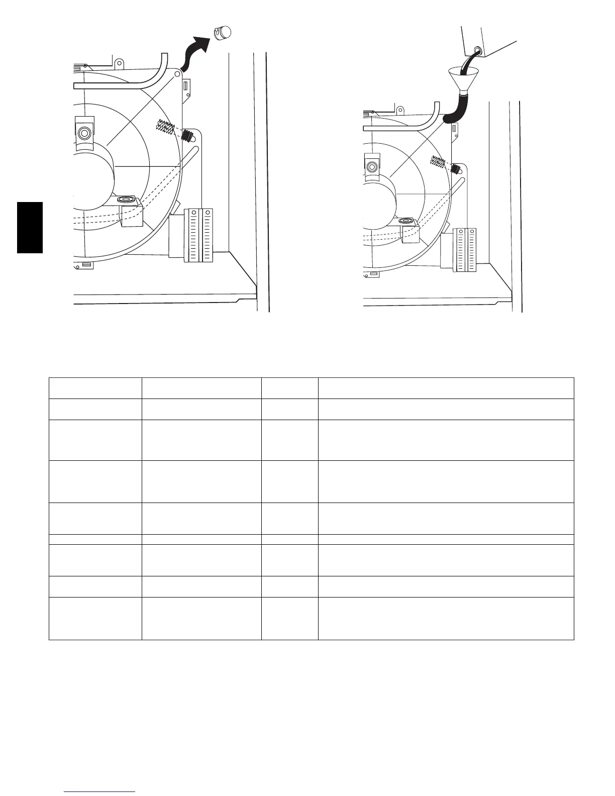
Fig. 50 -- Inducer Housing Drain Tube
A01050
Fig. 51 -- Filling Condensate Trap
Table 9 – Furnace Setup Switch Descriptio n
SETUP SWITCH
NO.
SWITCH NAME
NORMAL
POSITION
DESCRIPTION OF USE
SW1--1 Status Code Recovery OFF
Turn ON to retrieve up to 7 stored status codes for troubleshooting
assistance when R thermostat lead is disconnected.
SW1--2
Low Heat Only
(Adaptive Heat Mode when
OFF)
OFF
When SW1 --2 and SW4--2 are OFF allows step--modulating opera-
tion with a single stage thermostat. Turn ON when using 2 stage
thermostat to allow Low Heat operation when R to W/W1 closes
and Hi
h Heat o
eration
henRtoW/W1andW2close.
SW1--3
Low/Medium Heat Rise Ad-
just
OFF
Turn ON to increase Low and Medium Heat airflow by 18 percent.
This compensates for increased return air temperature caused with
bypass humidifier. This also increases the Low and Medium Heat
inducer speed 15 percent
SW1--4
Comfort/Efficiency Adjust-
ment
ON
Turn ON to decrease Low Heat airflow 9 percent,
Medium Heat airflow 7 percent,
and High Heat airflow 15 percent for maximum comfort.
SW1--5 CFM per ton adjust OFF Turn ON for 400 CFM per ton. Turn OFF for 350 CFM per ton.
SW1--6 Component Self Test OFF
Turn ON to initiate Component Self Test for troubleshooting
assistance when R thermostat lead is disconnected. Turn OFF
when Self T est is completed.
SW1--7
and SW1--8
Blower OFF delay ON or OFF
Blower Off Delay time.
See Table 6.
SW4--2
Medium Heat Only (Adap-
tive Heat Mode
when OFF)
OFF
When SW1 --2 and SW4--2 are OFF allows step--modulating opera-
tion with a single stage thermostat. Turn ON when using 2 stage
thermostat to allow Medium Heat operation when R to W/W1
closesandHighHeatoperationwhenRtoW/W1andW2close.
1. Remove upper inducer housing drain connection cap. (See
Fig. 50.)
2. Connect field-- supplied 1/2--in. ID tube to upper inducer
housing drain connection.
3. Insert field--supplied funnel into tube.
4. Pour 1 quart of water into funnel/tube. Water should run
through inducer housing, overfill condensate trap, and
flow into open field drain. (See Fig. 51.)
58MVC
 Loading...