EasyManuals Logo
Home>Carrier>Furnace>INFINITY ICS 58MVC

Carrier INFINITY ICS 58MVC User Manual

Carrier INFINITY ICS 58MVC
60 pages
To Next Page IconTo Next Page
To Previous Page IconTo Previous Page
Page #44 background imageLoading...
Page #44 background image
44
2. Locate setup switch SW4 on furnace control. (See Fig.
33.)
3. See Table 5 for setup switch description. (See Fig. 40 and
Fig. 49.)
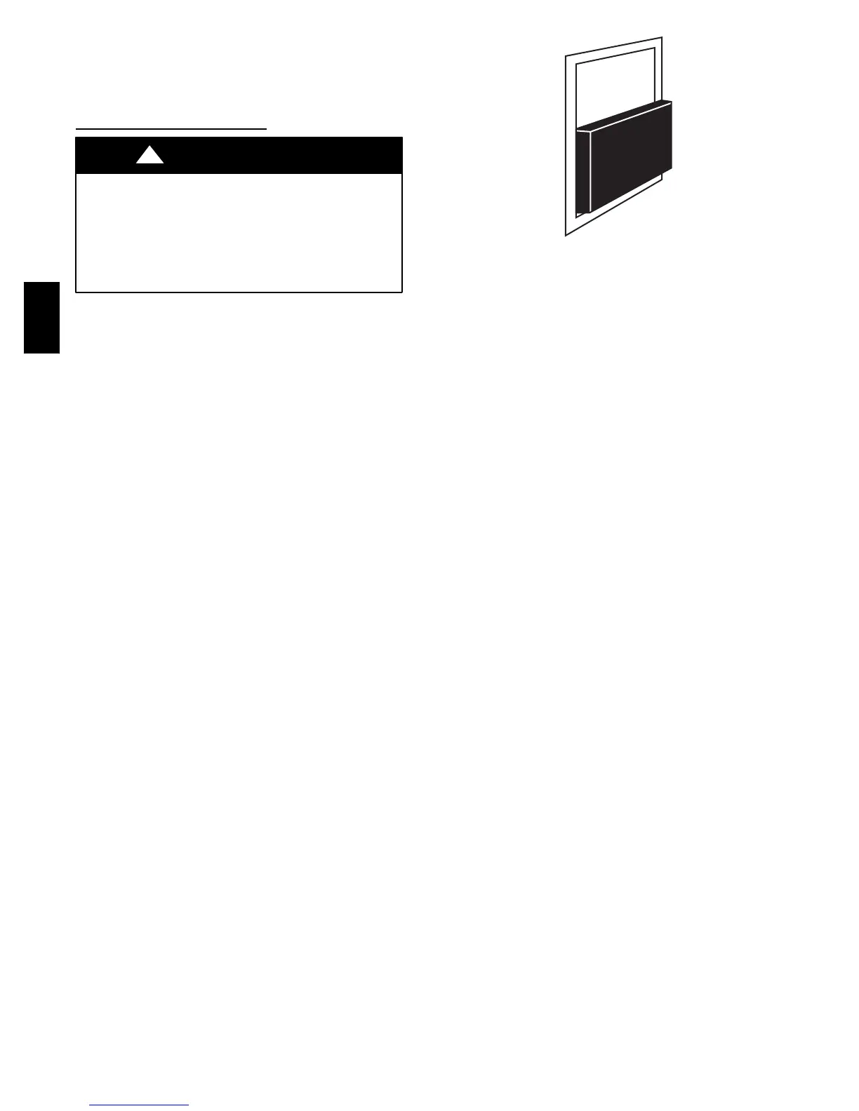
4. Replace main furnace door and blower access panel.
Prime Condensate Tra p with W
ater
UNIT OPERATION HAZARD
Failure to follow this caution may result in intermittent unit
operation or performance satisfaction.
Condensate trap must be PRIMED or proper d raining may
not occur. The condensate trap has two internal chambers
which can ONLY be primed by pouring water into the
inducer drain side of condensate trap.
CAUTION
!
A04001
Fig. 48 -- Example of Setup Switch in Off Position
58MVC

Table of Contents

Other manuals for Carrier INFINITY ICS 58MVC

Questions and Answers:

Question and Answer IconNeed help?

Do you have a question about the Carrier INFINITY ICS 58MVC and is the answer not in the manual?

Carrier INFINITY ICS 58MVC Specifications

Power IconPower
electrical supply voltage115 volts
electrical supply frequency60 Hz
electrical supply phasesingle-phase
Operating Environment IconOperating Environment
fuel gas efficiency92.1 to 95% AFUE
minimum air delivery_ _ _ cfm
external static pressure0.50 in. wc
Weight and Dimensions IconWeight and Dimensions
casing thickness0.030 in
depth_ in.
width_ in.
height_ in.

Related product manuals