57
UNIT DAMAGE HAZARD
Failure to follow this caution may result in component
damage.
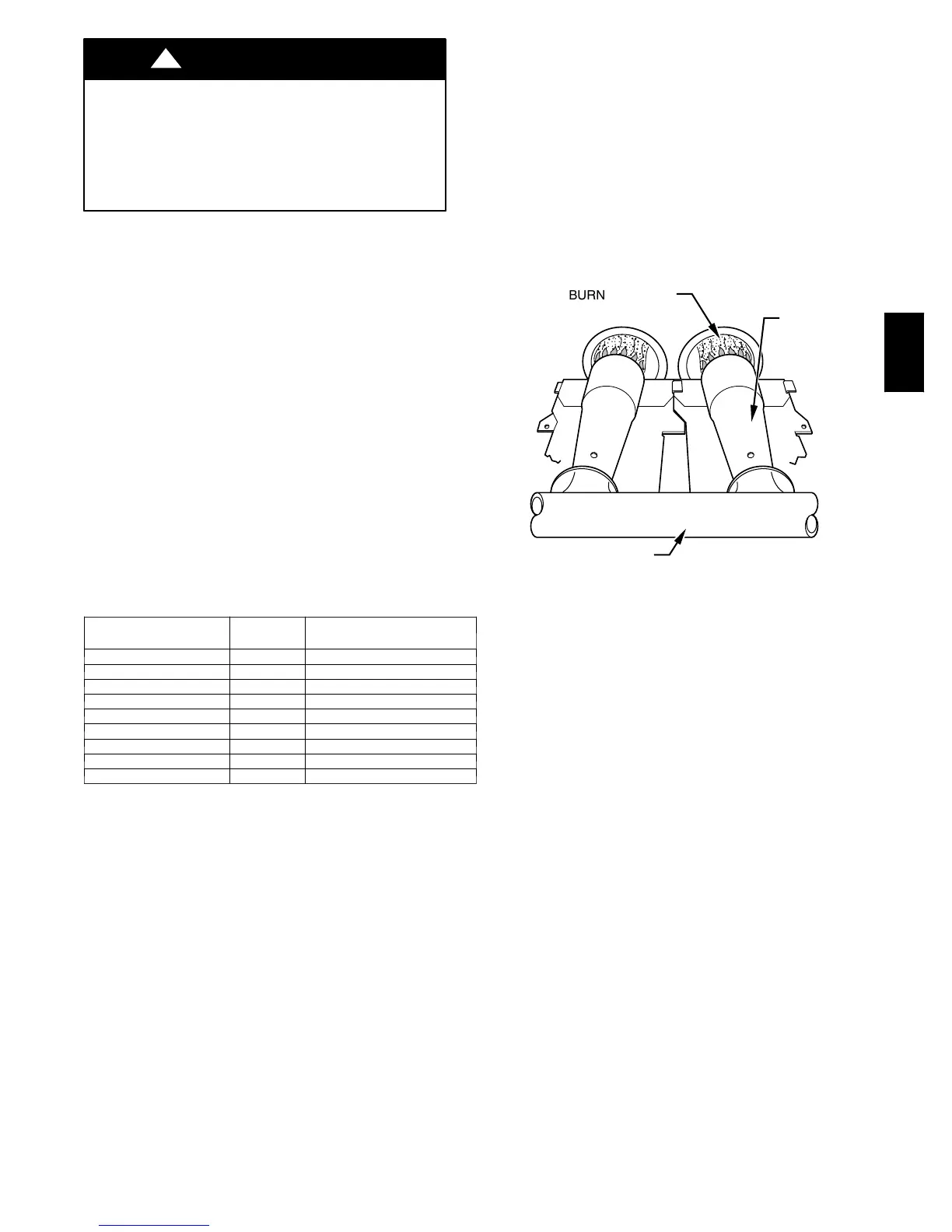
DO NOT redrill orifices. Improper drilling (burrs,
out-- of--round holes, etc.) can cause excessive burner noise
and misdirection of burner flames. (See Fig. 61.)
CAUTION
!
h. Jumper R to W/W1.
i. Let furnace run for 3 minutes in medium--heat operation.
j. Measure time (in sec) for gas meter to complete 1
revolution. Note reading.
k. Refer to Table 12 for cubic ft of gas per hr.
l. Multiply gas rate cu ft/hr by heating value (Btu/cu ft).
m. Move setup switch SW4--2 to OFF position and jumper
R and W/W1 and W2 thermostat connections. (See Fig.
33.) This keeps furnace locked in high--heat operation.
Repeat items i through l for high --heat operation.
EXAMPLE: (High--heat operation at 0 -- 2000 ft altitude)
Furnace input from rating plate is 80,000 Btuh
Btuh heating input = Btuh/cu ft X cu ft/hr
Heating value of gas = 975 Btuh/cu ft
Time for 1 revolution of 2--cu ft dial = 88 sec
Gas rate = 82 cu ft/hr (from Table 12)
Btuh heating input = 103 X 975 = 79,950 Btuh
In this example, the orifice size and manifold pressure adjustment
is within +/-- 2 percent of the furnace input rate.
n. Remove jumper across R, W/W1, and W2 thermostat
connections to terminate call for heat.
o. Wait for blower off--delay to finish then reset 115--v
power to furnace.
p. Jumper R and W/W1 thermostat connections on control
to start furnace.
q. Wait for the blower to turn ON then repeatitems i through
l for low--heat operation. This setting should not require
adjustment but if it does you will only have 15 minutes
to makethe adjustment. If you need moretime then move
setup switch SW1--2 on control center to ON position
(See Fig. 33).
NOTE: Measured gas inputs (high heat, medium heat, and low
heat) must be within +/--2 percent of that stated on furnace rating
plate when installed at sea level or derated as stated above when
installed at higher altitudes.
BURNER FLAME
BURNER
MANIFOLD
A89020
Fig. 62 -- Burner Flame
ALTITUDE
(FT)
%OF
DERATE
DERATE MULTIPLIER
FACTOR FOR U.S.A.*
0—2000 0 1.00
2001—3000 4—6 0.95
3001—4000 6—8 0.93
4001—5000 8—10 0.91
5001—6000 10—12 0.89
6001—7000 12—14 0.87
7001—8000 14—16 0.85
8001—9000 16—18 0.83
9001—10,000 18—20 0.81
*Derate mu l tiplier factor is based on midpoint altitude for altitude range.
Table 1 1 – Altitude Derate Multiplier for U.S.A.
58MVC
 Loading...