9
669224-R5
2.4 Custom Arm
Installation
Attachments without arms are supplied with two arm
bases. Special forks can be welded directly to them or
they can be used as a base to fabricate custom built arms.
WARNING: Cascade requires that a
qualified or certified welder experienced
in this type of fabrication be used for best
quality.
CAUTION: Weld fabricated arms to the arm bases only.
Do not weld or bolt special built arms or forks directly to
the arm bars.
The arm base material is AISI C-1020 HR with the following
specifications:
• TENSILE STRENGTH – 61,000 PSI (420 mPa) Minimum
• YIELD STRENGTH – 43,000 PSI (300 mPa) Minimum
• CARBON CONTENT – 23% Maximum
CAUTION: The surface flatness of the arm base must
remain within 0.10 in. (.25 mm) in capscrew area and arm
must slide manually.
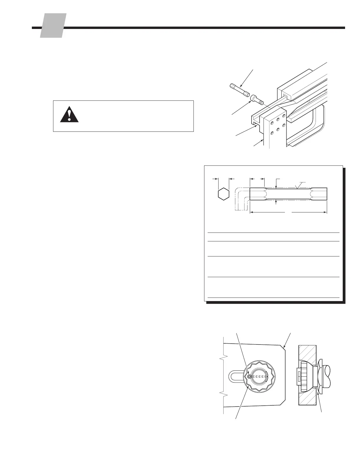
1 Fasten the arm bases to the arm bars. Tighten the
capscrews to the torque values indicated below
with a drive extension tool, 668020 (25D), 667699
(35D,40D,50D) or 676218 (70D,80D, 100D) to tighten
capscrews to the following torque values:
25D – 190–220 ft.-lbs. (257–298 Nm)
35D, 40D, 50D – 280–320 ft.-lbs. (380-434 Nm)
70D, 80D, 100D – 680–720 ft.-lbs. (922-976 Nm)
IMPORTANT: Be careful not to damage the arm bar.
Premature bearing failure will occur.
Short adapters care commercially available:
Williams .50 in. drive to .625 in. hex (25D) and .50
in. drive to .625 in. hex (35D, 40D, 50D) and .75 in.
drive to .75 in. hex (70D, 80D, 100D). Drive extension
dimensions are provided to make the tool from the allen
wrench. Do no use mild steel hex stock.
2 Lubricate the cylinder rod threads, nut threads and
spherical portion of the nut with wheel bearing grease.
3 Install the hex washer on the rod end with the beveled
side facing the lug.
4 Engage the rod end into the lug.
5 Tighten the rod end nut to the following torque values:
25D, 30D, 40D, 50D – 150–175 ft.-lbs. (203-–237 Nm)
70D, 80D, 100D – 225–250 ft.-lbs. (305–340 Nm)
Prevent rod turning by using wrench on hex washer.
NOTE: The rod nut is being tightened against the hex
washer. The nut will not be tight against the arm base
lug. This looseness allows for cylinder alignment during
clamping.
6 Install the locking cap and cotter pin.
7 Lubricate the bearing portion of the arm bars with a thin
film of chassis grease, if permitted by your application.
CL0457.ai
Drive Extension
Arm Bar
Arm Base
CL4232.ai
Arm Base Lug
Hex washers beveled
side facing lug
1
3
5
6
NSTALLATION
I
CL0456.eps
A
Hex
B
C
D
63
Dimensions – in. (mm)
Model A B C D
25D
.50
(12.7)
.75
(19.0)
.46
(11.6)
3.50
(88.0)
35D
40D
50D
.62
(15.7)
.50
(12.7)
.58
(14.7)
3.50
(88.0)
70D
80D
100D
.75
(19.0)
.50
(12.7)
.75
(19.0)
5.00
(127.0)
 Loading...