ROUBLESHOOTING
669224-R5
T
22
CL0257.eps
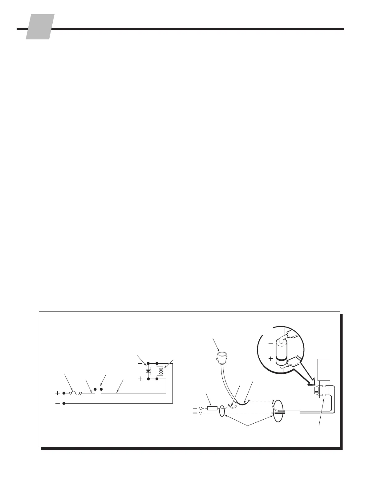
4.4 Electrical Circuit
(Solenoid Equipped Attachments)
Alongwiththefollowingprocedure,usetheelectrical
schematicanddiagramshown.
1 Checkthecontrolknobcircuitfuse.Replaceif
necessary.
2 Checkforlooseelectricalconnectionsatthetruck
ignitionswitch,controlknobbutton,solenoidcoil
terminalsanddiode.
3 Removethediodefromthesolenoidcoilterminal.Test
withanohmmeterforhighresistanceinonedirection
andnoresistanceintheotherdirection.Ifthereisno
resistanceinbothdirections,replacethediode.
NOTE:Whenreplacingthediode,thebanded(+)end
mustbeconnectedtothecoilandwiringasshown.
4 Disconnecttheelectricalleadsfromthesolenoidcoil
terminals.Useavoltmetertodetermineifvoltage
ispresentattheelectricalleadswhenthebuttonis
depressed.
• Ifthereisno current tothesolenoid,troubleshoot
theelectricalcircuitforshorts.
• Ifthereiscurrenttothesolenoid,testforcoil
continuity.
5 Testforcoilcontinuitybyplacinganohmmetertestlead
oneachsolenoidcoilterminal(ohmmeteronRx1scale).
• Ifthereisanohmmeterreading,thecoilisgood.
• Ifthecoilisgood,butthesolenoiddoesnot'click'
whenthecontrolknobbuttonisdepressed,the
solenoidcartridgemaybejammed.RefertoSection
5.8.
• Ifthereisnoohmmeterreading,thecoilisdefective
andshouldbereplaced.RefertoSection5.8.
CL0258.eps
7.5AmpFuse
7.5Amp
Fuse
White
White
Black
Black
KnobButton
(Normally
Open)
SolenoidCoil
SolenoidCoil
Diode
Diode
UserSuppliedWire
ControlLeverKnob
withPush-button
 Loading...