- 8 -
Trouble shooting ECR V1.01
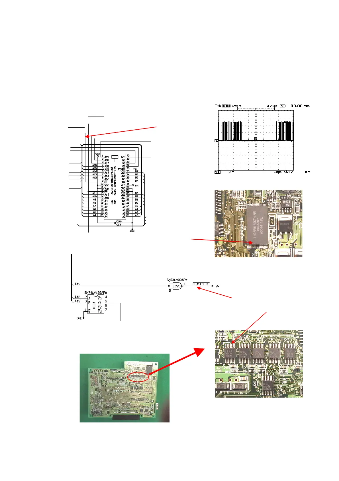
3) Check the poor connection between CPU and RAM or Flash ROM1.
Specially, check the Flash ROM1 connection to re-solder the all lines.
4) Check the RAM1 or Flash ROM1 chip enable signal.
5) If the signals of the address bus and the data bus are not stable (Ex: After some time,
the all signal becomes GND level or so on.), replace “IC10” of the CPU to new one.
[ Flash ROM1 chip enable signal ]
Flash ROM1 chip enable signal
Flash ROM1 chip enable
Flash ROM1 pin No.9
Flash ROM1 IC6
Flash RST
Flash ROM1 chip enable
Bottom side of Main PCB
Pin No.3 of IC25 (74LV00)
Flash1 CE
Address bus
 Loading...