V-R200 / VER.1
– 40 –
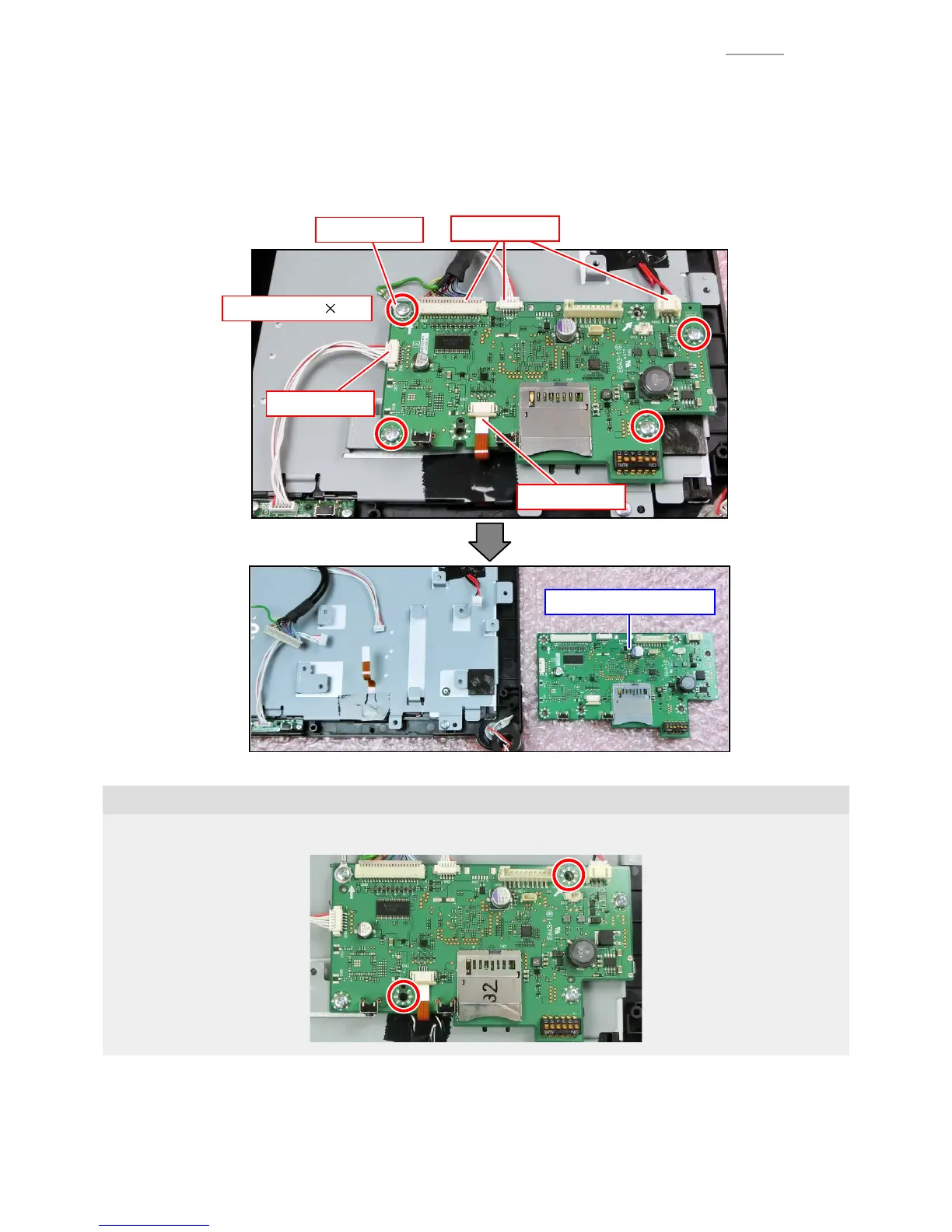
A-5. Removal of the main PCB (PCB ASSY/E843-1)
(1) Unlock the connector lock and disconnect the FPC.
(2) Disconnect four connectors.
(3) Undo four screws.
(4) Replace the main PCB (PCB ASSY/E843-1) with a new one.
(1) FPC
(2) Connectors
(2) Connector
Ground wire
(3) Screw (S2) 4
(4)
PCB ASSY/E843-1
Note on reassembling
0
In this stage, the two places shown below are not fastened with screws yet.
A-6. Assemble the parts in the reverse order of the disassembly procedure.
 Loading...