V-R200 / VER.1
– 41 –
B. Replacing the LCD Unit
Supplementary explanation
When the CASE ASSY/FRONT is replaced with a spare part one.
• Carry out the touch panel calibration.
Refer to: Diagnostic operation
1-4. Touch panel calibration
Model with no Dallas key
B-1. Remove the REAR CASE.
Reference Procedure: A-1 to A-3
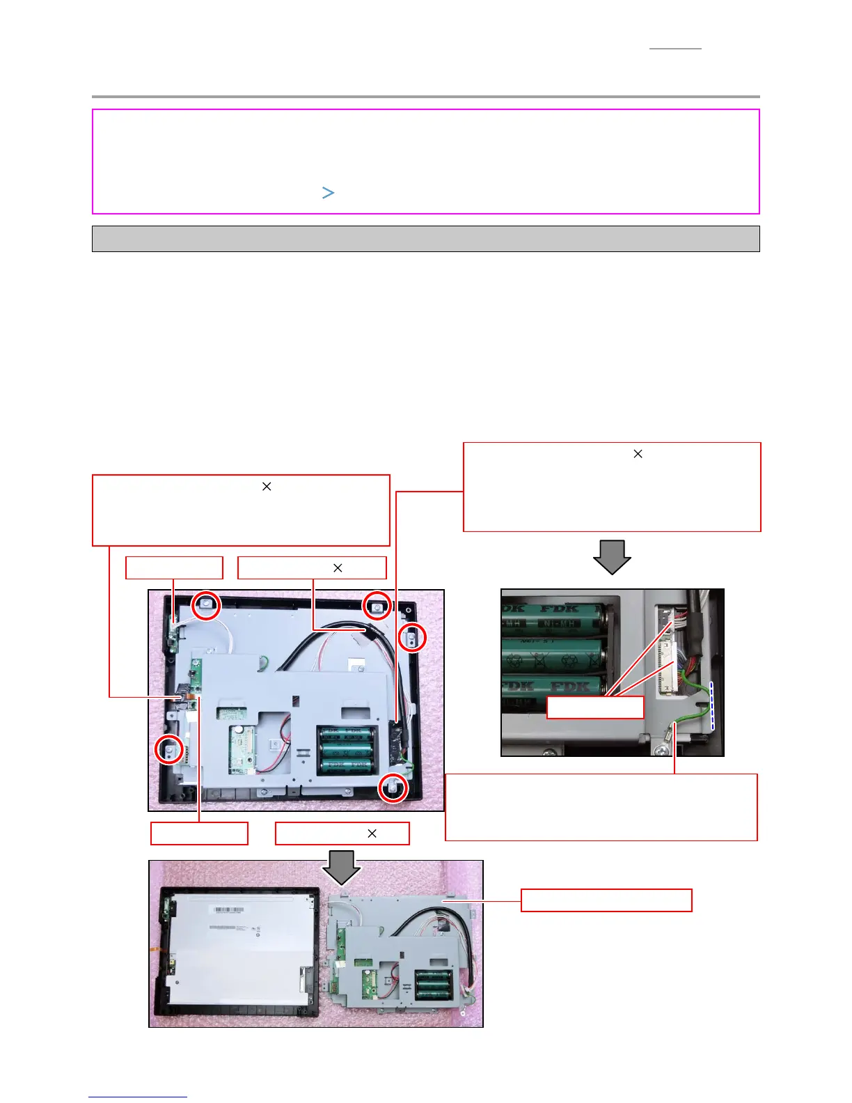
B-2. Removal of the CHASSIS/LCD
(4) Screw (S4) 5
(3) Connector
(1) Tape (
15 50)
(1) Tape (
15 50)
NOTE: There is a connector under the tape. Peel
off the tape without giving a load to the
connector.
(3) Connectors
(1) Tape (
15 30)
NOTE: Peel off the tape without giving a load to
the FPC.
(2) FPC
(1) Peel off tape (3 pcs.).
(2) Unlock the connector lock and disconnect the FPC.
(3) Disconnect three connectors.
(4) Undo fi ve screws.
(5) Remove the CHASSIS/LCD block.
(5) CHASSIS/LCD
block
Note on reassembling
Ground wire
When attaching the ground wire, make sure that the
wire does not protrude from the CHASSIS/LCD.
 Loading...