2110 Temperature Controller
Chromalox 2110
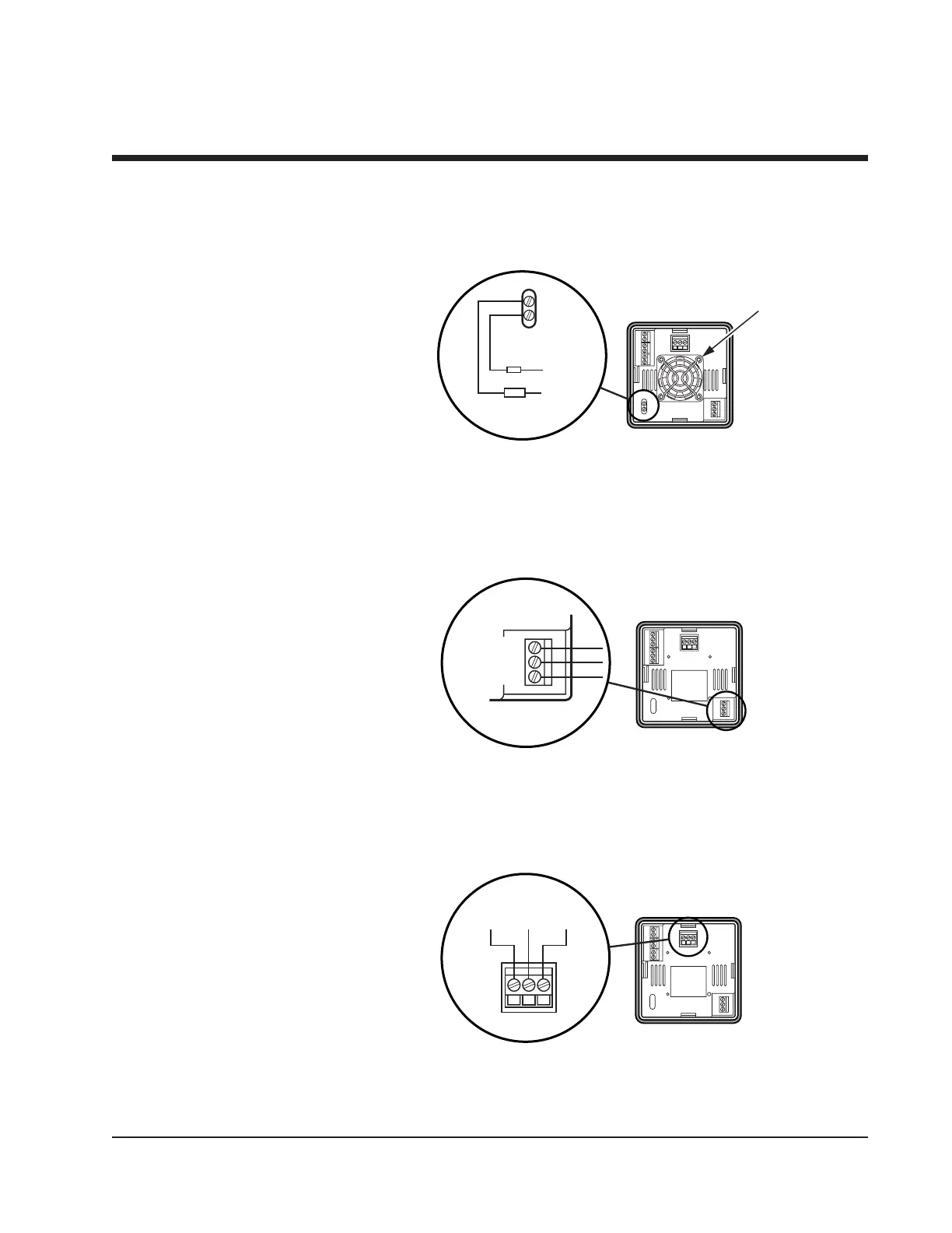
Figure 3.12
Control Output Wiring–S1 and S2
S1 (Solid State Relay, 5 Amps) and
S2 (Solid State Relay, 10 Amps) Output Wiring
Note: 2110 model S2 has a fan. 2110 model S1 does not have a fan.
11
NC
NO
COM
Fuse
Load
120/240
VAC
Neutral
Instrument Power
Wiring
Make 120 or 240 VAC instrument power connections to terminals as
shown in Figure 3.13.
Alarm Wiring
The Form C Relay Output is connected as shown in Figure 3.14.
Figure 3.13
90-260 VAC Instrument Power Connections
Figure 3.14
Alarm Connections
CNO
Alarm Out
NC
NC
NO
COM
NC
NO
COM
120/240VAC
Neutral
Ground
NC
NO
COM
Section 3–Installation and Wiring
Control Output
Wiring
continued
Fan

 Loading...

