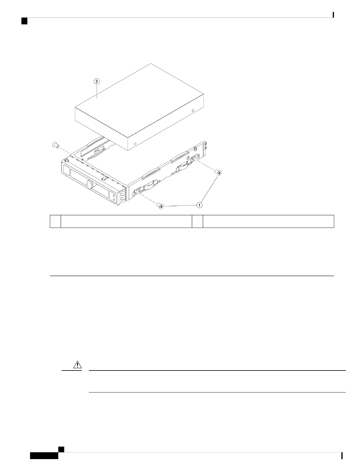
Figure 35: Remove the Drive Tray
Drive removed from drive tray2Drive tray screws (two on each side)1
Step 3 Install a new drive:
a) Place a new drive in the empty drive tray and install the four drive-tray screws.
b) With the ejector handle on the drive tray open, insert the drive tray into the empty drive bay.
c) Push the tray into the slot until it touches the backplane, and then close the ejector handle to lock the drive in place.
Remove and Replace a Power Supply
The chassis ships with two power supplies, which are redundant and hot-swappable. One is the active power
supply and the other is the standby power supply (1+1).
This chassis also supports cold redundancy. Depending on the power being drawn by the chassis, one power
supply might actively provide all power to the system while the remaining power supply is put into a standby
state. For example, if the power consumption can be satisfied by power supply 1, then power supply 2 is put
into a standby state.
When you replace power supplies, do not mix power supply types in the chassis. Both power supplies must
be the same wattage and Cisco PID.
Caution
Cisco Secure Firewall Management Center 1700, 2700, and 4700 Hardware Installation Guide
38
Installation, Maintenance, and Upgrade
Remove and Replace a Power Supply
 Loading...