14
Cisco 2500 Series Wireless Controller Getting Started Guide
Installing the Controller
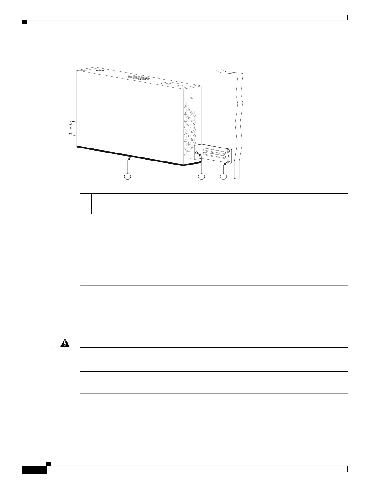
Figure 6 Mounting the Controller on the Wall
Step 3 After the controller is mounted on the wall, perform the following tasks to complete the installation:
• Connecting the Controller Console Port
• Securing the Power Adapter Cable
• Connecting to the Network
Step 4 For configuration instructions about using the CLI setup program, see the “Running the Bootup Script
and Power-On Self Test” section on page 20.
Mounting the Controller on a Wall (Mounting Screws)
When mounting the 2504 controller on a wall using mounting screws, always mount the controller with
the front panel facing down.
Warning
Read the wall-mounting carefully before beginning installation. Failure to use the correct hardware
or to follow the correct procedures could result in a hazardous situation to people and damage to the
system.
Statement 378
To mount the controller on a wall using mounting screws, follow these steps:
Step 1 Mark the location of the mounting screws on the wall. Use the mount hole locations on the back of the
controller for placement of the mounting screws (Figure 7). (The mount holes are shown in Figure 7 with
a cross-hatch mark.)
1 Front panel (facing down) 3 Wall mounting screws
2 #10-32 flat head screws
282085
2
31

 Loading...