29
Cisco 2500 Series Wireless Controller Getting Started Guide
Connecting to the Network
Note With Release 7.4, directly connected local mode APs via two PoE (Power over Ethernet) ports are
supported. Directly connected APs were not supported before Release 7.4.
You have prepared the controller for basic operation. Refer to the Cisco Wireless Controller
Configuration Guide for information on configuring the controller to meet the specific needs of your
wireless network.
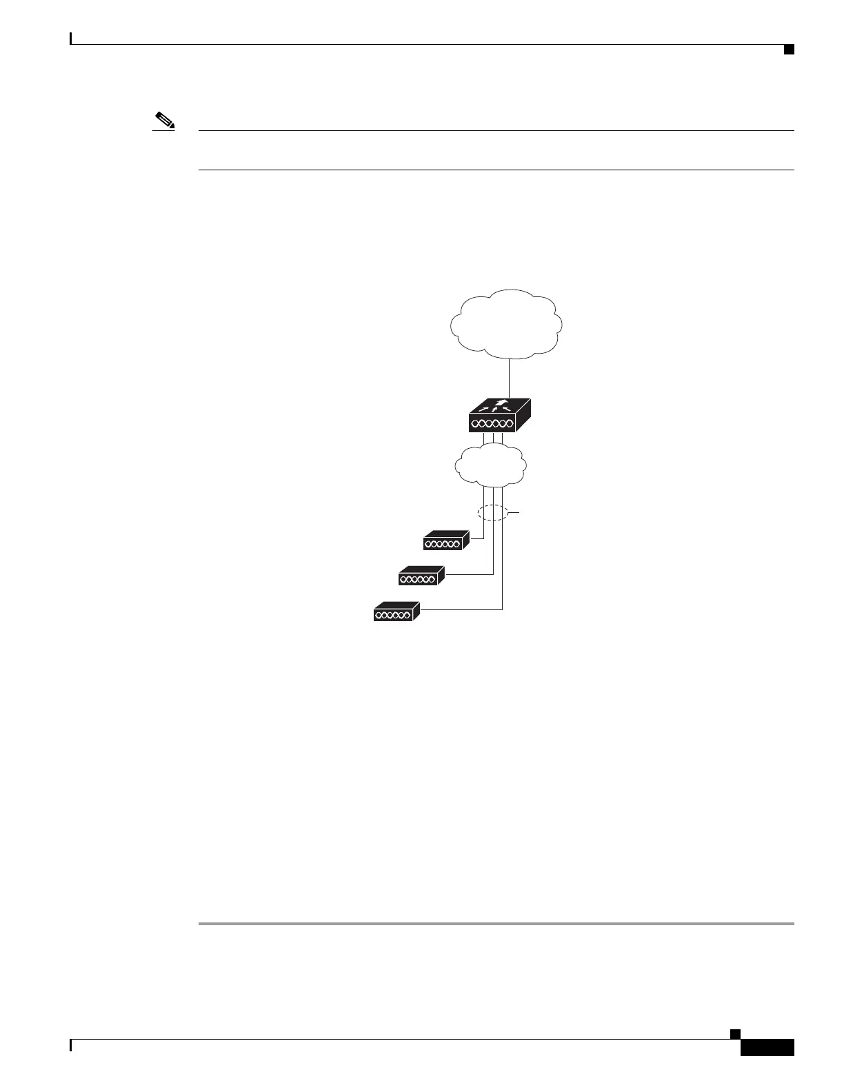
Figure 14 Access Points Connected to a Controller
Checking the Controller LEDs
If your 2504 controller is not working properly, check the LEDs on the front panel of the unit. You can
use the LED indications to quickly assess the status of the unit. See Table 1 on page 4 for a description
of the front panel LEDs.
The installation is complete. Refer to the Cisco Wireless Controller Configuration Guide for more
information about configuring your controller. The guide is available on cisco.com.
Using the Reset Button
The Reset button on the front panel of the controller becomes active after the controller boots. To reset
the controller using the Reset button, follow these steps:
Step 1 Connect a PC to the controller console point.
Step 2 Press and hold the Reset button for at least 3 seconds using a pointed object, such as a ball point pen,
pencil, or paper clip.
282081
10/100/1000BASE-T
MDI cables
10/100/1000BASE-T
MDI cable
Cisco Access Points
Network
Cisco 2504 Wireless
Controller
Network

 Loading...