▀ Features and Functionality
▄ Cisco ASR 5000 Series Product Overview
After passing through the Token Bucket Algorithm, the packet is internally classified with a color, as follows:
If there are not enough tokens in the PBS bucket to allow a packet to pass, the packet is considered to be in
violation and is marked ―red‖ and the violation counter is incremented by one.
If there are enough tokens in the PBS bucket to allow a packet to pass, but not in the CBS ―bucket‖, then the
packet is considered to be in excess and is marked ―yellow‖, the PBS bucket is decremented by the packet size,
and the exceed counter is incremented by one.
If there are more tokens present in the CBS bucket than the size of the packet, then the packet is considered as
conforming and is marked ―green‖ and the CBS and PBS buckets are decremented by the packet size.
The system can be configured with actions to take for red and yellow packets. Any of the following actions may be
specified:
Drop: The offending packet is discarded.
Transmit: The offending packet is passed.
Lower the IP Precedence: The packet's ToS octet is set to ―0‖, thus downgrading it to Best Effort, prior to
passing the packet.
Different actions can be specified for red and yellow, as well as for uplink and downlink directions and for different
3GPP traffic classes.
DSCP Marking for IPSec Access
The Differentiated Service Code Point (DSCP) marking feature on the PDG/TTG provides support for more granular
configuration of DSCP marking.
The PDG/TTG functioning as a TTG can perform DSCP marking of packets sent over the Wu interface in the downlink
direction to the WLAN UEs and over the Gn' interface in the uplink direction to the GGSN.
In the PDG Service Configuration Mode of the system‘s CLI, you use the command to control DSCP
markings for downlink packets sent over the Wu interface in IPSec tunnels, and use the
command to control DSCP markings for uplink packets sent over the Gn' interface in GTP tunnels.
The DSCP markings are applied to the IP header of every transmitted subscriber data packet. DSCP levels can be
assigned to specific traffic patterns in order to ensure that the data packets are delivered according to the precedence
with which they are tagged. The four traffic patterns have the following order of precedence: background (lowest),
interactive, streaming, and conversational (highest).
For the interactive traffic class, the PDG/TTG supports per-gateway service and per-APN configurable DSCP marking
for the uplink and downlink directions based on Allocation/Retention Priority in addition to the current priorities.
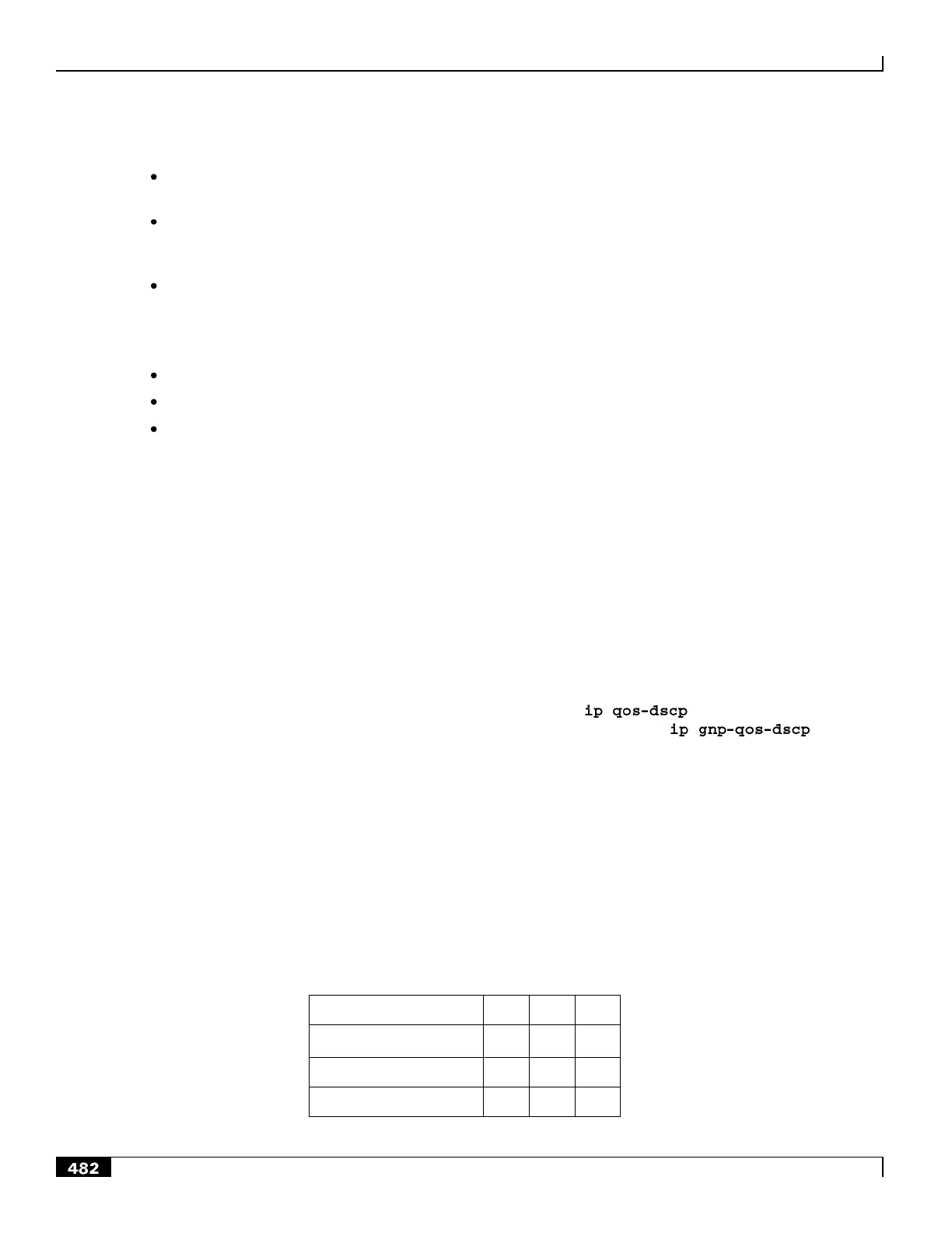
The following matrix can be used to determine the DSCP markings used based on the configured traffic class and
Allocation/Retention Priority:
Table 69. Default DSCP Value Matrix
Traffic Handling Priority

 Loading...


