Step 3 Route the cable through the cable-management bracket and carefully press the cable into the channel so it is
held in place by the cable clips, as shown in Figure 185: Interface Cable Routing Using the Line Card Cable
Management Bracket , on page 183.
• For an example of cable routing in the Cisco ASR 9006 Router, see Figure 186: Interface Cable Routing
Using the Line Card and Chassis Cable Management Bracket on the Cisco ASR 9006 Router, on page
184.
• For an example of cable routing in the Cisco ASR 9904 Router, see Figure 187: Interface Cable Routing
Using the Line Card and Chassis Cable Management Bracket on the Cisco ASR 9904 Router, on page
184.
• For an example of cable routing in the Cisco ASR 9910 Router, see Figure 188: Interface Cable Routing
Using the Line Card and Chassis Cable Management Bracket on the Cisco ASR 9910 Router , on page
185.
Step 4 Insert the cable connector into its assigned port.
Step 5 Repeat Step 1 through Step 4 for each additional cable connection to that line card.
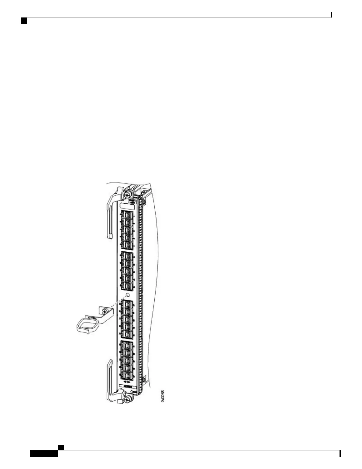
Figure 184: Attaching a Line Card Cable Management Bracket
Cisco ASR 9000 Series Aggregation Services Router Hardware Installation Guide
182
Installing Cards and Modules in the Chassis
Connecting Line Card Network Interface Cables

 Loading...


