Installing an Interface Module
Procedure
Step 1
Before inserting an interface module, make sure that the chassis is grounded.
Step 2
To insert the interface module, carefully align the edges of the interface module between the upper and lower edges of the
router slot.
Step 3
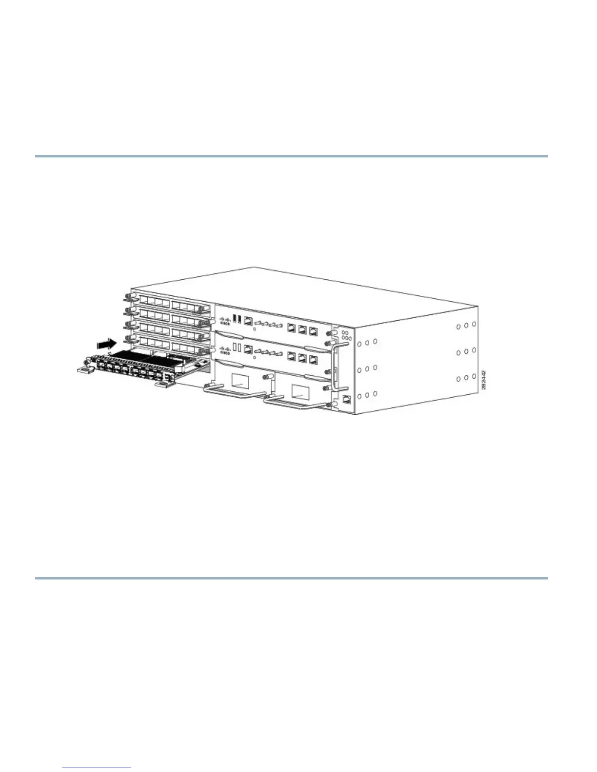
Carefully slide the interface module into the router slot until the interface module makes contact with the backplane. The
figure below shows how to install the interface module.
Figure 10: Inserting an Interface Module
Step 4
Tighten the locking thumbscrews on both sides of the interface module. The recommended maximum torque is 5.5 in.-lb
(.62 N-m).
Step 5
Connect all the cables to each interface module.
Close all unused SFP ports using SFP dust caps to prevent dust from accumulating inside the cage. The dust caps
(Cisco part number A900-DCAP-SFP-S= (24 caps per package) or Cisco part number A900-DCAP-SFP-L= (240
caps per package)) can be ordered from Cisco.
Note
10 Gigabit Ethernet interface modules on the A900-RSP1 modules and A900-RSP2A-64 module are not supported
in slots 4 and 5.
Note
Close all unused RJ-45, SFP, XFP, and QSFP ports on the interface module using the appropriate dust caps to
prevent dust from accumulating inside the cage. For information on dust caps, see Installing Dust Caps section
in the Cisco ASR 903 and ASR 903U Aggregation Services Router Hardware Installation Guide.
Note
Do not use interface module and power supply ejector handles to lift the chassis; using the handles to lift the
chassis can deform or damage the handles.
Caution
Installing the Power Supply
The Cisco ASR 903 Router provides the following power supply:
•
DC power
14

 Loading...


