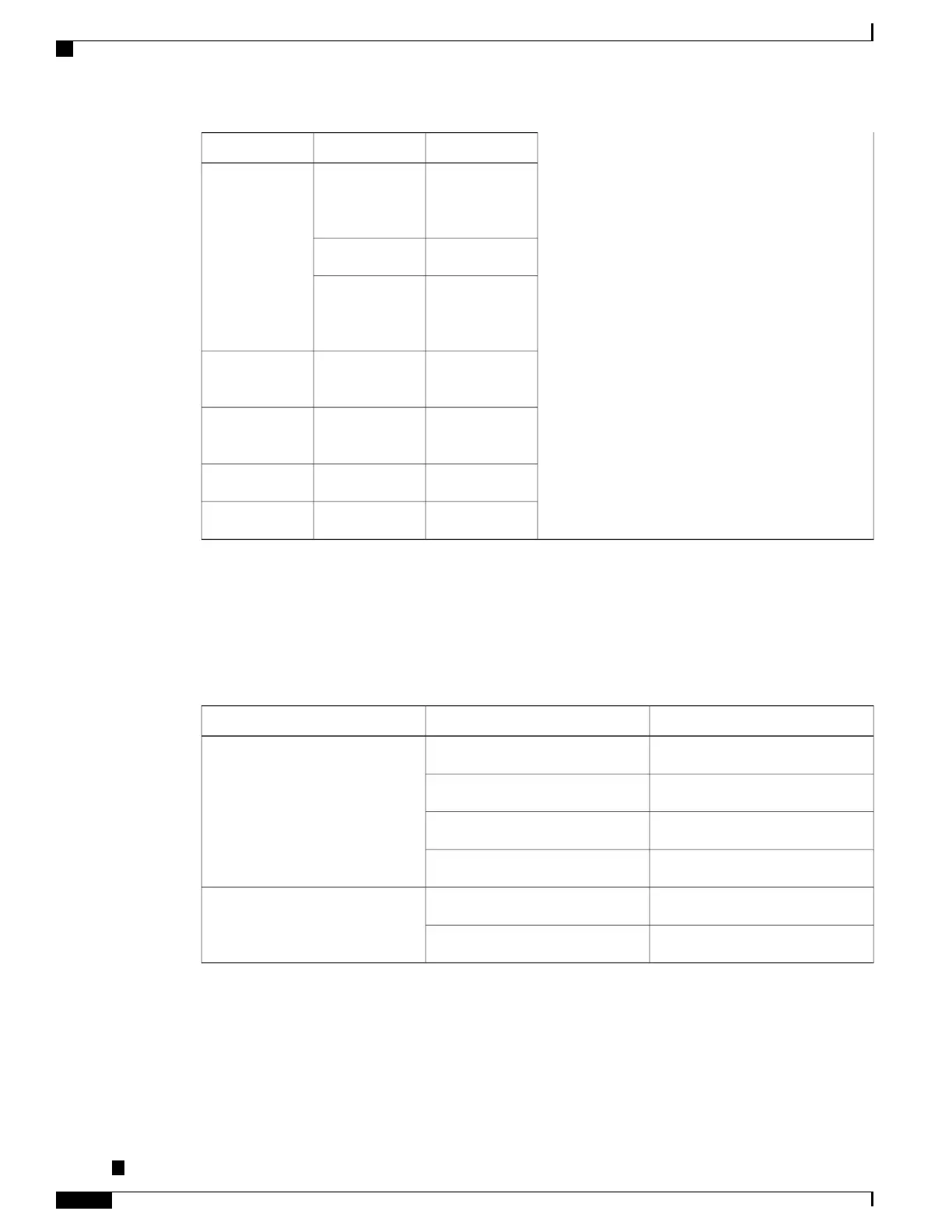
IndicationLED StateLED
All power rails
are within
supported range
GreenPower (PWR)
DisabledRed
No power to the
Interface
Module
Off
FailedRedOperating
Status(STAT)
Disabled or
powered-down
Off
BootingBlinking red
ActiveGreen
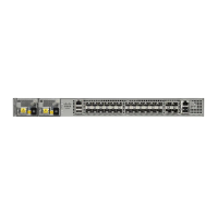
RJ-45 LEDs
Each RJ-45 port has two LED indicators. Left LED indicates the Link status; right LED indicates the status
of the duplex LED.
Table 10: RJ-45 LED Indication
IndicationLED StateLED
Link up in 10/100/1000Base-TGreenLeft
Activity in 10/100/1000Base-TBlinking Green
Fault/ErrorYellow
Link downOff
Link up in full duplexGreenRight
Link up in half duplexOff
Power Supply Unit LEDs
Each power supply unit has a corresponding LED on the front panel.
Cisco ASR-920-24SZ-IM, ASR-920-24SZ-M, ASR-920-24TZ-M Aggregation Services Router Hardware Installation
Guide
20
Overview
External Interfaces
 Loading...