Procedure
Step 1 Remove the rubber plugs from the module port and fiber-optic cable, and store them for future use.
Step 2 Insert one end of the fiber-optic cable into the SFP module port.
Step 3 Insert the other cable end into a fiber-optic connector on a target device.
Step 4 Observe the port status LED.
The LED turns green when the router and the target device have an established link.
If the LED is off, the target device might not be turned on, there might be a cable problem, or there might be
problem with the adapter installed in the target device.
Step 5 If necessary, reconfigure and restart the router or target device.
Installing the Chassis Ground Connection
Before you connect the power or turn on the power to the router, you must provide an adequate chassis ground
(earth) connection to your router.
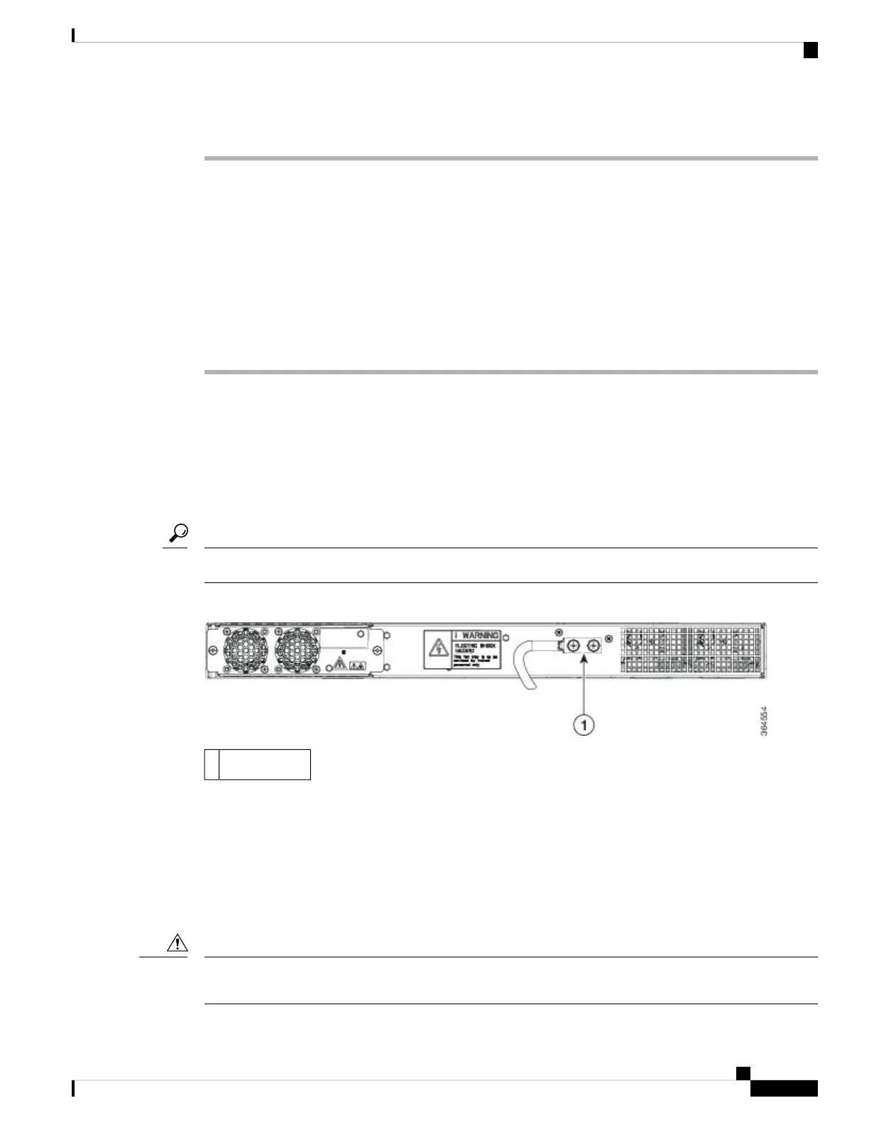
This section describes how to ground the chassis. The grounding lug location is on the back panel of the router.
Ensure that the grounding lug wire does not cover the fan opening.
Tip
Figure 14: Attaching a Grounding Lug to the Rear of the Router
Grounding-lug1
To ensure that the chassis ground connection that you provide is adequate, you need the following parts and
tools:
• Ratcheting torque screwdriver with Phillips head that exerts up to 15 in.-lb (1.69 N-m) of torque for
attaching the ground wire to the router
• Crimping tool as specified by the ground lug manufacturer
• 6-AWG or larger copper wire for the ground wire
• Wire-stripping tools appropriate to the wire you are using
Before making connections to the router, ensure that you disconnect the power at the circuit breaker. Otherwise,
severe injury to you or damage to the router may occur.
Caution
Installing the Cisco ASR 920 Series Router
17
Installing the Cisco ASR 920 Series Router
Installing the Chassis Ground Connection

 Loading...